292
Bosch Rexroth AG
| Tightening Technology
3 608 878 300
System 350
| 3 608 878 300/2019-03
6.4.2
Results output via field bus
6.4.2.1
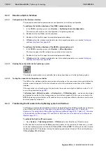
Configuration of the field bus interface
The required communication parameters are configured via the interface configuration.
To configure the field bus interface of the CS351 compact system:
1.
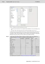
In the BS350 operating system, click
System
Tightening channel configuration.
This function calls up the current configuration of a tightening channel.
2.
Double click the line
CS
to view the interfaces.
3.
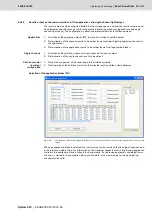
Double click the line
A
to open the associated parameters dialog.
4.
At
Code
, select the interface module and enter the required parameters, see section
To configure the field bus interface of the KE350 communication unit:
1.
In the BS350 operating system, click
System
KE configuration.
This function opens the KE configuration currently on the controller.
2.
Double click the line
A
to open the associated parameters dialog.
3.
At
Code
, select the interface module and enter the required parameters, see section
6.4.2.2
Sending the configuration to the tightening system
The interface configuration is only valid after the settings have been sent to the tightening system.
6.4.2.3
Testing the connection to the partner controller
The LEDs on the interface modules communicate information on the connection status and whether the
module is ready-to-operate. For further information, refer to the individual instructions of the interface
modules.
If the connection is not functioning at the point when the results are output via field bus, a class 1 or 3
error will be generated
.
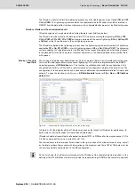
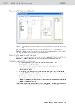
The
System test
KE field bus data…
or
System test
CS field bus data …
can be used to display
and analyze the contents of the storage areas on the interface module. With this, you can check in the
BS350 operating system whether an ID code has been correctly transmitted or whether a results value
has been properly configured.
6.4.3
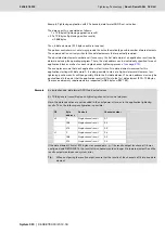
Transferring the ID codes to the tightening system via field bus
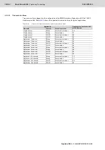
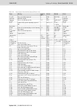
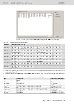
The ID code is transferred by the field bus master to the data buffer of the field bus interface as a character
string (ASCII) (see
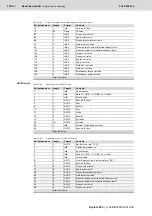
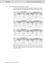
Table 6–45: Allocation of the data buffer for IMpdp
,
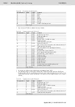
Allocation of the data buffer for IMdev, IMmtcp, IMenip and IMenip2
,
and
Table 6–48: Allocation of the data buffer for IMpnio and
).
To activate the field bus ID-code source:
Go to
System
Tightening cell data
ID Code
and select Field bus as ID code source.
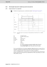
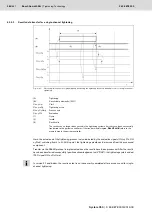
An ID code that is transferred to the IMpdp interface module / in the control unit of channel x.y, is used
for the next tightening process (started with
CH x.y CW
or
CH x.y CCW
). The ID code must be stored in
the data input field 100 ms before starting the tightening and remain stored until the end of tightening
(
CH x.y CyCmp
,
FO x CyCmp
).
Содержание Rexroth Tightening System 350
Страница 4: ...4 641 Bosch Rexroth AG Schraubtechnik System 350 3 608 878 300 2019 03 ...
Страница 120: ...120 641 Bosch Rexroth AG Tightening Technology 3 608 878 300 System 350 3 608 878 300 2019 03 ...
Страница 194: ...194 641 Bosch Rexroth AG Tightening Technology 3 608 878 300 System 350 3 608 878 300 2019 03 ...
Страница 638: ...638 641 Bosch Rexroth AG Tightening Technology 3 608 878 300 System 350 3 608 878 300 2019 03 ...

