


19
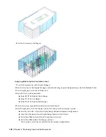
Draw rectangles or closed polylines for the stairwells to enclose the start and end of the stair and its landing.
20
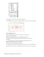
On the Insert menu, click Xref Manager.
You can also click
at the bottom right of the drawing area to display the Xref Manager dialog box.
21
In the Xref Manager dialog box, select Typical Core, press and hold CTRL, and select Stair Towers.
22
Click Detach, and click OK.
Cut holes in the slab
23
Click
on the Zoom flyout on the Navigation toolbar to zoom to the extents of the drawing.
24
Select the slab, right-click, and click Hole
➤
Add.
25
Select one of the rectangular polylines, and press ENTER.
26
Enter
y
(Yes) to erase the layout geometry, and press ENTER.
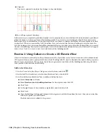
27
Repeat steps 24 through 26 for each of the other rectangular polylines.
Holes have been generated in the slab based on the perimeters of the polylines.
28
Save all open project drawings.
In this exercise, you added four elevators to the typical core and cut holes in the floor slab to provide openings for the
two centrally located elevator shafts and the stairwells. Next, you complete the interior of the building model by adding
the plumbing fixtures in the bathrooms.
In this lesson, you finished the building core by adding emergency exit stairs, anchored railings, and elevators. You
cut holes for the elevator shaft and stairwells.
132 | Chapter 3 Developing Your Building Model Design
Содержание 18506-091462-9305 - Architectural Desktop 2006
Страница 1: ...AUTODESK ARCHITECTURAL DESKTOP 2006 Imperial Tutorials Update August 2005 ...
Страница 6: ...iv Contents ...
Страница 142: ...136 Chapter 3 DevelopingYour Building Model Design ...
Страница 290: ...284 Chapter 5 Creating a Steel Framed Residence ...


