12
Contents
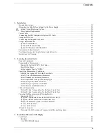
Setting the Horizontal Axis of the Graph for the List Sweep. . . . . . . . . . . . . . . . . . . . . . . . . . . . . . . . . 124
Setting Measurement Accuracy, Stability, and Time . . . . . . . . . . . . . . . . . . . . . . . . . . . . . . . . . . . . . . . . . 126
Setting measurement bandwidth. . . . . . . . . . . . . . . . . . . . . . . . . . . . . . . . . . . . . . . . . . . . . . . . . . . . . . . 126
Averaging between sweeps (sweep-to-sweep averaging) . . . . . . . . . . . . . . . . . . . . . . . . . . . . . . . . . . . 126
Averaging for each measurement point (point averaging) . . . . . . . . . . . . . . . . . . . . . . . . . . . . . . . . . . . 127
6. Calibration
Selecting Appropriate Calibration Method . . . . . . . . . . . . . . . . . . . . . . . . . . . . . . . . . . . . . . . . . . . . . . . . 130
A. Calibration When Using Direct Connection Type Test Fixture. . . . . . . . . . . . . . . . . . . . . . . . . . . . . . . 133
B. Calibration for Four-Terminal Pair, 1-m Extension. . . . . . . . . . . . . . . . . . . . . . . . . . . . . . . . . . . . . . . . 135
Fixture Compensation When the 16451B is Used . . . . . . . . . . . . . . . . . . . . . . . . . . . . . . . . . . . . . . . . . 136
C. Calibration for Four-Terminal Pair, 2-m Extension. . . . . . . . . . . . . . . . . . . . . . . . . . . . . . . . . . . . . . . . 137
D. Calibration When an Exclusive Fixture is Connected to the 42942A. . . . . . . . . . . . . . . . . . . . . . . . . . 139
E. Calibration When the 7-mm Port of the 42942A is Extended . . . . . . . . . . . . . . . . . . . . . . . . . . . . . . . . 141
F. Calibration When a Probe Adapter is Connected to the 42941A. . . . . . . . . . . . . . . . . . . . . . . . . . . . . . 143
G. Calibration When the 3.5-mm Port of the 42941A is Extended . . . . . . . . . . . . . . . . . . . . . . . . . . . . . . 145
User Calibration . . . . . . . . . . . . . . . . . . . . . . . . . . . . . . . . . . . . . . . . . . . . . . . . . . . . . . . . . . . . . . . . . . . . . 147
User Calibration Procedure. . . . . . . . . . . . . . . . . . . . . . . . . . . . . . . . . . . . . . . . . . . . . . . . . . . . . . . . . . . 147
Turning User Calibration On/Off . . . . . . . . . . . . . . . . . . . . . . . . . . . . . . . . . . . . . . . . . . . . . . . . . . . . . . 148
Defining Standard Values for User Calibration . . . . . . . . . . . . . . . . . . . . . . . . . . . . . . . . . . . . . . . . . . . 148
Port Extension Compensation . . . . . . . . . . . . . . . . . . . . . . . . . . . . . . . . . . . . . . . . . . . . . . . . . . . . . . . . . . 150
Fixture Compensation . . . . . . . . . . . . . . . . . . . . . . . . . . . . . . . . . . . . . . . . . . . . . . . . . . . . . . . . . . . . . . . . 151
Fixture compensation procedure. . . . . . . . . . . . . . . . . . . . . . . . . . . . . . . . . . . . . . . . . . . . . . . . . . . . . . . 151
Turning the fixture compensation on or off . . . . . . . . . . . . . . . . . . . . . . . . . . . . . . . . . . . . . . . . . . . . . . 153
Defining the standard values for fixture compensation . . . . . . . . . . . . . . . . . . . . . . . . . . . . . . . . . . . . . 153
Selecting Calibration/Compensation Data Points . . . . . . . . . . . . . . . . . . . . . . . . . . . . . . . . . . . . . . . . . . . 155
List of fixed calibration/compensation frequency points . . . . . . . . . . . . . . . . . . . . . . . . . . . . . . . . . . . . 156
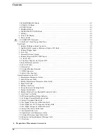
7. Setting Up the Display of Measurement Results
Selecting the Measurement Parameters . . . . . . . . . . . . . . . . . . . . . . . . . . . . . . . . . . . . . . . . . . . . . . . . . . . 158
Selecting the Graph Axis Format . . . . . . . . . . . . . . . . . . . . . . . . . . . . . . . . . . . . . . . . . . . . . . . . . . . . . . . . 160
When Using Cartesian Coordinates . . . . . . . . . . . . . . . . . . . . . . . . . . . . . . . . . . . . . . . . . . . . . . . . . . . . 160
When Using Complex Parameters (COMPLEX Z-Y) . . . . . . . . . . . . . . . . . . . . . . . . . . . . . . . . . . . . . . 162
Auto-scaling the Trace . . . . . . . . . . . . . . . . . . . . . . . . . . . . . . . . . . . . . . . . . . . . . . . . . . . . . . . . . . . . . . . . 164
Manual Scale Setting (for measurements other than COMPLEX Z-Y). . . . . . . . . . . . . . . . . . . . . . . . . . . 166
Scaling the Trace Based on the Reference Line and Resolution per Division . . . . . . . . . . . . . . . . . . . . 166
Scaling the Trace Based on the Top and Bottom Values . . . . . . . . . . . . . . . . . . . . . . . . . . . . . . . . . . . . 169
Manually Scaling the Active Trace for a COMPLEX Z-Y Graph . . . . . . . . . . . . . . . . . . . . . . . . . . . . . . . 172
Scaling the Active Trace for a Complex Plane. . . . . . . . . . . . . . . . . . . . . . . . . . . . . . . . . . . . . . . . . . . . 172
Scaling the Active Trace for a Polar Chart . . . . . . . . . . . . . . . . . . . . . . . . . . . . . . . . . . . . . . . . . . . . . . . 175
Selecting the Target Trace Type (Data or Memory) . . . . . . . . . . . . . . . . . . . . . . . . . . . . . . . . . . . . . . . . . . 177
Enabling or Disabling Coupled Scaling Mode. . . . . . . . . . . . . . . . . . . . . . . . . . . . . . . . . . . . . . . . . . . . . . 178
Trace-based Comparison and Calculation . . . . . . . . . . . . . . . . . . . . . . . . . . . . . . . . . . . . . . . . . . . . . . . . . 179
Identifying Differences between Data and Memory Traces through Comparison or Calculation . . . . . 179
Subtracting an Offset Value . . . . . . . . . . . . . . . . . . . . . . . . . . . . . . . . . . . . . . . . . . . . . . . . . . . . . . . . . . 184
Superimposing Multiple Traces . . . . . . . . . . . . . . . . . . . . . . . . . . . . . . . . . . . . . . . . . . . . . . . . . . . . . . . . . 185
Comparing traces using the list sweep function . . . . . . . . . . . . . . . . . . . . . . . . . . . . . . . . . . . . . . . . . . . 186
Monitoring the Test Signal Level (AC) . . . . . . . . . . . . . . . . . . . . . . . . . . . . . . . . . . . . . . . . . . . . . . . . . . . 189
Содержание 4294A
Страница 1: ......
Страница 2: ......
Страница 4: ......
Страница 5: ......
Страница 6: ......
Страница 8: ......
Страница 16: ...8 ...
Страница 30: ...22 Chapter1 Installation Power Cable Figure 1 2 Alternative Power Cable Options ...
Страница 70: ...62 Chapter3 Front Rear Panel and LCD Display Items Displayed on the LCD ...
Страница 100: ...92 Chapter5 Setting Measurement Conditions Setting Sweep Range Figure 5 7 After MKR CENTER Figure 5 8 ...
Страница 101: ...Chapter 5 93 Setting Measurement Conditions Setting Sweep Range 5 Setting Measurement Conditions Figure 5 9 ...
Страница 106: ...98 Chapter5 Setting Measurement Conditions Setting Number of Points NOP Figure 5 13 Number of points 801 ...
Страница 330: ...322 Chapter9 Setting Using Control and Management Functions Performing Self Diagnosis of the Agilent 4294A ...
Страница 436: ...428 AppendixB Key Definitions Softkeys displayed by pressing the Recall key ...
Страница 454: ...446 AppendixC Error messages WRONG I O PORT DIRECTION ...
Страница 462: ...454 AppendixD Initial Settings Initial Settings Settings that can be Saved Recalled Settings that can be Backed Up ...
Страница 468: ......


