Chapter 3
57
Front/Rear Panel and LCD Display
Items Displayed on the LCD
3
. F
ront/
R
ear
P
ane
l a
nd
L
CD Di
sp
la
y
on the dc bias monitor feature through the keystroke sequence
[Display]
-
BIAS MON [ ]
-
VOLT/CURRENT
.
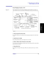
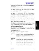
12. Sweep Stop/Span Value Field
This field shows the sweep stop or span value that is currently in effect. Use the
[Stop]
key
to set the sweep stop value and the
[Span]
key to set the sweep span value.
13. Test Signal Current Level Monitor Field
This field shows the AC current level monitor value for the test signal that is currently in
effect. For this field to actually display the monitor value, you must turn on the test signal
level monitor feature through the keystroke sequence
[Display]
-
OSC MON on OFF
.
14. Test Signal Level/CW Frequency Setting Field
This field shows the test signal level setting for frequency sweep or the CW frequency
setting for test signal level sweep or dc bias sweep. Use the [Source] key to change the
current value.
15. Test Signal Voltage Level Monitor Field
This field shows the AC voltage level monitor value for the test signal that is currently in
effect. For this field to actually display the monitor value, you must turn on the test signal
level monitor feature through the keystroke sequence
[Display]
-
OSC MON on OFF
.
16. Sweep Start/Center Value Field
Shows the start or center value for the sweep settings that are currently in effect. Use the
[Start]
key to set the sweep start value and the
[Center]
key to set the sweep center value.
17. Instrument Status Area
This area shows the status of various functions of the instrument.
Trace validity
*
After you have changed the measurement conditions, this indicator is
displayed until you update the measurement trace with the new
settings. To get a correct measurement trace, you must update the trace
so that this indicator disappears.
dc bias status
DCB
Indicates that the instrument is performing measurement under dc
voltage bias conditions (in variable voltage mode) or dc current bias
conditions (in variable current mode).
VC
Indicates that the instrument is performing measurement under dc
voltage bias conditions (in constant voltage mode).
IC
Indicates that the instrument is performing measurement under dc
current bias conditions (in constant current mode).
Содержание 4294A
Страница 1: ......
Страница 2: ......
Страница 4: ......
Страница 5: ......
Страница 6: ......
Страница 8: ......
Страница 16: ...8 ...
Страница 30: ...22 Chapter1 Installation Power Cable Figure 1 2 Alternative Power Cable Options ...
Страница 70: ...62 Chapter3 Front Rear Panel and LCD Display Items Displayed on the LCD ...
Страница 100: ...92 Chapter5 Setting Measurement Conditions Setting Sweep Range Figure 5 7 After MKR CENTER Figure 5 8 ...
Страница 101: ...Chapter 5 93 Setting Measurement Conditions Setting Sweep Range 5 Setting Measurement Conditions Figure 5 9 ...
Страница 106: ...98 Chapter5 Setting Measurement Conditions Setting Number of Points NOP Figure 5 13 Number of points 801 ...
Страница 330: ...322 Chapter9 Setting Using Control and Management Functions Performing Self Diagnosis of the Agilent 4294A ...
Страница 436: ...428 AppendixB Key Definitions Softkeys displayed by pressing the Recall key ...
Страница 454: ...446 AppendixC Error messages WRONG I O PORT DIRECTION ...
Страница 462: ...454 AppendixD Initial Settings Initial Settings Settings that can be Saved Recalled Settings that can be Backed Up ...
Страница 468: ......


