


Chapter 3
51
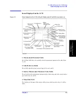
Front/Rear Panel and LCD Display
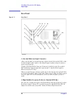
Rear Panel
3
. F
ront/
R
ear
P
ane
l a
nd
L
CD Di
sp
la
y
3. External Trigger Input
Allows you to input a TTL-compatible signal to trigger the execution of measurement.
When the signal shows a rising or falling edge between the LOW and HIGH states, a
measurement cycle is triggered. Before you can trigger measurement by inputting a signal
through this connector, you have to specify that the trigger signal be input from an external
trigger source (via the external trigger input). To do so, use the keystrokes:
[Trigger]
-
SOURCE [ ]
-
EXTERNAL
. For more information on the input signal conditions specific to
this connector, refer to Chapter 10 , “Specifications and Supplemental Performance
Characteristics,” on page 323.
4. LAN Port
Allows you to connect the Agilent 4294A with a local area network (LAN). The “Tx”
(transmit) LED located on the right-hand side of the LAN port is lit while the Agilent
4294A is outputting data over the local area network. For more information on working
with a local area network, refer to the
Programming Manual
.
5. Internal Reference Output
Connects to the external reference input terminal of another instrument to phase lock it to
the Agilent 4294A.
6. External Program RUN/CONT Input
Allows you to input a TTL-compatible signal that triggers the RUN or CONTINUE
command for an HP Instrument BASIC program. When the signal shows a rising or falling
edge between the LOW and HIGH states, then the command is triggered. For more
information on the input signal conditions specific to this connector, refer to Chapter 10 ,
“Specifications and Supplemental Performance Characteristics,” on page 323.
7. 8-bit I/O Port
Provides a data communications interface with an external device such as a handler on a
production line. This port supports 4-bit data for input and 8-bit data for output.
8. Time Base Adjuster (for Option 1D5)
This adjuster is used to fine-tune the operating frequency of the Agilent 4294A when it is
equipped with Option 1D5 (High Stability Frequency Reference).
NOTE
This is intended for service center use only. Do not attempt to adjust the operating
frequency yourself.
9. Mini-DIN Keyboard Port
A PS/2 port intended for connecting a 101-key English keyboard. You can use a keyboard
to facilitate entry operations such as creating and executing HP Instrument Basic programs
or entering display titles.
NOTE
This port only supports a 101-key English keyboard with a PS/2 connector. Do not attempt
Содержание 4294A
Страница 1: ......
Страница 2: ......
Страница 4: ......
Страница 5: ......
Страница 6: ......
Страница 8: ......
Страница 16: ...8 ...
Страница 30: ...22 Chapter1 Installation Power Cable Figure 1 2 Alternative Power Cable Options ...
Страница 70: ...62 Chapter3 Front Rear Panel and LCD Display Items Displayed on the LCD ...
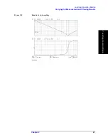
Страница 100: ...92 Chapter5 Setting Measurement Conditions Setting Sweep Range Figure 5 7 After MKR CENTER Figure 5 8 ...
Страница 101: ...Chapter 5 93 Setting Measurement Conditions Setting Sweep Range 5 Setting Measurement Conditions Figure 5 9 ...
Страница 106: ...98 Chapter5 Setting Measurement Conditions Setting Number of Points NOP Figure 5 13 Number of points 801 ...
Страница 330: ...322 Chapter9 Setting Using Control and Management Functions Performing Self Diagnosis of the Agilent 4294A ...
Страница 436: ...428 AppendixB Key Definitions Softkeys displayed by pressing the Recall key ...
Страница 454: ...446 AppendixC Error messages WRONG I O PORT DIRECTION ...
Страница 462: ...454 AppendixD Initial Settings Initial Settings Settings that can be Saved Recalled Settings that can be Backed Up ...
Страница 468: ......


