background image

452

Appendix D


Initial Settings

Initial Settings, Settings that can be Saved/Recalled, Settings that can be 
Backed Up

Analysis

Equivalent 
circuit 
analysis

Equivalent 
circuit model

Selection

A

¬

¬

Ö

Display

Off

¬

¬

Ö

Equivalent 
circuit 
parameter

Display

Off

¬

¬

Ö

Value

0

¬

¬

Ö

Statistical analysis

Off

¬

¬

Ö

Trace 
bandwidth 
analysis

On/Off

Off

¬

¬

Ö

Cutoff point 
definition

Definition type

Fixed

¬

¬

Ö

Fixed value

0

¬

¬

Ö

Waveform 
analysis 
(GPIB 
command 
only)

Analysis range

Full sweep range

¬

¬

Ö

Analyzed segment when sweep type is list

0

¬

¬

Ö

Analyzed trace (Data/Memory)

Data

¬

¬

Ö

Peak definition

0

¬

¬

Ö

Limit test

On/Off

Off

¬

¬

Ö

Beep On/Off

Off

¬

¬

Ö

Limit line table

Empty

¬

¬

Ö

Limit range 
offset

Limit value (X-axis) offset

0

¬

¬

Ö

Sweep parameter value (Y-axis) offset

0

¬

¬

Ö

Save, recall 
and so on

Contents selection 
for saving data arrays

Data array

Off

¬

¬

Memory array

Off

¬

¬

Data trace array

On

¬

¬

Memory trace array

On

¬

¬

User calibration data and fixture 
compensation data array

Off

¬

¬

Storage device selection

Floppy Disk Drive No effect

¬

Ö

Status report 
structure 
(GPIB 
command 
only)

Service request enable register value

0

No effect

¬

Standard event status enable register value

0

No effect

¬

Instrument event status enable register value

0

No effect

¬

Operation status enable register value

0

No effect

¬

Positive transition filter value of operation status register

0

No effect

¬

Negative transition filter value of operation status 
register

0

No effect

¬

LAN/GPIB

4294A IP address

0.0.0.0

No effect

¬

Ö

Gateway IP address

0.0.0.0

No effect

¬

Ö

Subnet mask

0.0.0.0

No effect

¬

Ö

4294A GPIB address

17

No effect

¬

Ö

Controller GPIB address

21

No effect

¬

Ö

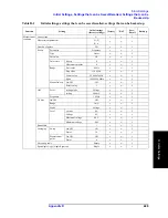
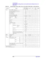
Table D-1 

Initial settings, settings that can be saved/recalled, settings that can be backed up

Function

Setting

Initial settings 

(factory settings)

[Preset]

*RST

Save/ 

Recall

Backup

Содержание 4294A

Страница 1: ......

Страница 2: ......

Страница 3: ...instrument If you continue to operate without repairing the instrument there is a potential fire or shock hazard for the operator n Instrument operates abnormally n Instrument emits abnormal noise smell smoke or a spark like light during the operation n Instrument generates high temperature or electrical shock during operation n Power cable plug or receptacle on instrument is damaged n Foreign sub...

Страница 4: ......

Страница 5: ......

Страница 6: ......

Страница 7: ...ghly sensitive microcircuits in your instrument ESD damage is most likely to occur as the test fixtures are being connected or disconnected Protect them from ESD damage by wearing a grounding strap that provides a high resistance path to ground Alternatively ground yourself to discharge any static charge built up by touching the outer shell of any grounded instrument chassis before touching the te...

Страница 8: ......

Страница 9: ...ration Manual Seventh Edition FIRMWARE REVISIONS This manual applies directly to instruments that have the firmware revision 1 1x For additional information about firmware revisions see Appendix A Part No 04294 90060 February 2003 Printed in Japan ...

Страница 10: ...ishi Ku Kobe shi Hyogo 651 2241 Japan Copyright 1999 2001 2002 2003 Agilent Technologies Japan Ltd Manual Printing History The manual s printing date and part number indicate its current edition The printing date changes when a new edition is printed Minor corrections and updates incorporated in reprints do not necessitate a new printing date The manual part number changes when extensive technical...

Страница 11: ... Do not operate the instrument in the presence of inflammable gasses or fumes Operation of any electrical instrument in such an environment clearly constitutes a safety hazard Keep Away from Live Circuits Operators must not remove instrument covers Component replacement and internal adjustments must be made by qualified maintenance personnel Do not replace components with the power cable connected...

Страница 12: ... current On Supply Off Supply In position of push button switch Out position of push button switch Frame or chassis terminal A connection to the frame chassis of the equipment which normally includes all exposed metal structure WARNING This warning sign denotes a hazard It calls attention to a procedure practice or condition that if not correctly performed or adhered to could result in injury or d...

Страница 13: ...ice facility designated by Agilent Technologies Buyer shall prepay shipping charges to Agilent Technologies and Agilent Technologies shall pay shipping charges to return the product to Buyer However Buyer shall pay all shipping charges duties and taxes for products returned to Agilent Technologies from another country Agilent Technologies warrants that its software and firmware designated by Agile...

Страница 14: ...when a term is defined For example icons are symbols Italic Italic type is used for emphasis and for titles of manuals and other publications Hardkey Indicates a hardkey labeled Hardkey Softkey Indicates a softkey labeled Softkey Hardkey Softkey1 Softkey2 Indicates keystrokes Hardkey Softkey1 Softkey2 Agilent 4294A Documentation Map The following manuals are available for the Agilent 4294A Operati...

Страница 15: ...ints on getting the most use from it and includes a general programming reference It is divided into three books HP Instrument BASIC Programming Techniques HP Instrument BASIC Interface Techniques and HP Instrument BASIC Language Reference Service Manual Agilent P N 04294 90100 Option 0BW only This manual explains how to adjust and repair the Agilent 4294A and how to carry out performance tests Th...

Страница 16: ...8 ...

Страница 17: ...surement Conditions 33 Initialize the Agilent 4294A to the Preset State 33 Select Z q as the Measurement Parameter 33 Select Frequency as the Sweep Parameter 33 Select Logarithmic Sweep as the Sweep Type 33 Set the Sweep Start Value to 100 Hz 34 Set the Sweep Stop Value to 100 MHz 34 Set the Measurement Bandwidth to 2 34 Fixture Compensation 35 Perform Fixture Compensation for the Open Circuit Sta...

Страница 18: ... box 52 Items Displayed on the LCD 53 1 Measurement Parameter Fields 53 2 Scale Reference Fields 53 3 Marker Measurement Parameter Value Fields 53 4 Menu Title Field 53 5 Softkey Label Area 54 6 Sweep Parameter Reading Fields 55 7 Marker Status Fields 55 8 Marker Statistics Trace Bandwidth Analysis Fields 56 9 Limit Line Test Fields 56 10 HP Instrument Basic Status Indicator 56 11 dc Voltage Curre...

Страница 19: ... Specified Point 100 Setting Time Delay for Measurement 102 Setting with sweep time 102 Setting with time delay at measurement point 102 Setting with sweep time delay 103 Setting Fixed Frequency CW Frequency 104 Setting Oscillator Level 105 Selecting Unit for Oscillator Level Voltage or Current 106 Setting and Applying dc Bias 107 1 Selecting dc bias mode 107 2 Setting fixed dc bias level 107 3 Se...

Страница 20: ...compensation procedure 151 Turning the fixture compensation on or off 153 Defining the standard values for fixture compensation 153 Selecting Calibration Compensation Data Points 155 List of fixed calibration compensation frequency points 156 7 Setting Up the Display of Measurement Results Selecting the Measurement Parameters 158 Selecting the Graph Axis Format 160 When Using Cartesian Coordinates...

Страница 21: ...arker 217 Moving the delta marker alone to place it at a reference point 218 Displaying the main sub marker and reading the difference from the reference point 219 Reading actual measurement points only reading interpolated values between measurement points 222 Search the maximum minimum measurements 223 Search the point of target measurement 225 Search the maximum minimum peak 228 Define the Peak...

Страница 22: ... for automatic setting when power is on 291 Recall the saved file 292 Print the measurement results and internal data with a printer 294 Set the print form color resolution and how to handle the paper 294 Print the measurements in graphic representation 296 Print the measurements and settings text 296 9 Setting Using Control and Management Functions Re displaying an Instrument Message 300 Setting ...

Страница 23: ...er Functions 344 Equivalent Circuit Analysis 345 Limit Line Test 345 Mass Storage 345 Parallel Printer Port 345 GPIB 346 HP Instrument BASIC 346 8 Bit I O Port 346 24 bit I O Port Handler Interface 346 LAN Interface 348 General Characteristics 349 External Reference Input 349 Internal Reference Output 349 High Stability Frequency Reference Output Option 1D5 349 External Trigger Input 349 External ...

Страница 24: ...390 Softkeys displayed by pressing the Marker key 392 Softkeys displayed by pressing the Marker key 395 Softkeys displayed by pressing the Search key 397 Softkeys displayed by pressing the Utility key 402 Softkeys displayed by pressing the System key 404 Softkeys displayed by pressing the Local key 415 Softkeys displayed by pressing the Copy key 417 Softkeys displayed by pressing the Save key 421 ...

Страница 25: ...ins installation and setup instructions for the Agilent 4294A Precision Impedance Analyzer For information on connecting test accessories such as a test fixture adapter probe or measurement cable refer to Chapter 4 Preparation of Measurement Accessories ...

Страница 26: ...r on self test fails contact the nearest Agilent Technologies office If the shipping container is damaged or the cushioning material shows signs of unusual stress notify the carrier as well as the Agilent Technologies office Save the shipping materials for the carrier s inspection Table 1 1 Contents of the Agilent 4294A package Agilent product part number1 Description Quantity 4294A 4294A Precisio...

Страница 27: ...ation Manual Pro gramming Manual and Sample Program Disk 4 Not supplied unless the product is purchased with Option 0BW 5 Not supplied unless the product is purchased with Option 810 with keyboard 6 This accessory varies from country to country For the power cable option see Figure 1 2 7 Not supplied unless the product is purchased with option ID5 High Stability Frequency Reference 8 Not supplied ...

Страница 28: ...30 Spare fuses are available from your nearest Agilent Technologies Sales and Service Office You can check and replace the fuse by dismounting the fuse folder shown in Figure 1 1 To dismount the fuse holder first disconnect the power cable then use a flat blade screwdriver or similar tool to push the portion marked a in Figure 1 1 upward so that the holder surface rises up a little and finally pul...

Страница 29: ...nds the instrument frame through one of the three wires The type of power cable shipped with each instrument depends on the country of destination Refer to Figure 1 2 for the part numbers of the power cables available WARNING For protection against electrical shock the power cable grounding prong must not be removed The power plug must be plugged into an outlet that provides an appropriate recepta...

Страница 30: ...22 Chapter1 Installation Power Cable Figure 1 2 Alternative Power Cable Options ...

Страница 31: ...Only When Option 1D5 is installed connect the BNC cable that comes with this option between the REF OVEN and EXT REF INPUT connectors on the rear panel of the Agilent 4294A Option 1D5 makes the frequency of the Agilent 4294A s test signal both more stable and more accurate Figure 1 3 Connecting the BNC Adapter for Option 1D5 Only ...

Страница 32: ... 45J UTP Unshielded Twisted Pair LAN connector provided on the rear panel Step 1 To connect the 4294A to a LAN securely insert the LAN cable into the LAN port Step 2 For the 4294A to communicate over a LAN you must set up the network connection as described in the section Using LAN in the Programming Manual Figure 1 4 Using the LAN Port ...

Страница 33: ...board into the keyboard connector on the rear panel Step 2 Set the keyboard in a comfortable position NOTE Do not put anything on the keyboard Doing so can cause an error during the power on self test Figure 1 5 Connecting the Supplied Keyboard 1 The Agilent 4294A comes with a keyboard if it is purchased with Option 810 with keyboard ...

Страница 34: ...nstalling the Rackmount Handle Kit Option 1CN Handle Kit Option 1CN includes a pair of handles and the parts necessary for attaching the handles to the Agilent 4294A Installing the Handles Step 1 Remove the adhesive backed trim strips 1 from the left and right side faces of the front panel frame Figure 1 6 Step 2 Attach the front handles 3 to the side faces with the supplied screws Table 1 2 Rackm...

Страница 35: ...aces with the supplied screws Step 3 Remove all four legs from the bottom face by pulling up the tabs and sliding the legs out in the direction indicated by the arrows Step 4 Mount the 4294A on the rack Option 1CP Rackmount Handle Kit Option 1CP includes two flanges and two handles along with their attachments Mounting the Agilent 4294A on a Rack with Handles Step 1 Remove the adhesive backed trim...

Страница 36: ...roduct or for the rackmount type by forcefully air cooling inside the rack housing For information on ambient temperature to satisfy the specifications and measurement accuracy of the product refer to Chapter 10 Specifications and Supplemental Performance Characteristics on page 323 When the ambient temperature around the product is kept within the temperature range of the operating environment sp...

Страница 37: ...g Operation Basics This chapter guides you through a tour of the basic measurement functions of the Agilent 4294A Precision Impedance Analyzer If you are new to the Agilent 4294A this tutorial should help you get familiar with the instrument ...

Страница 38: ... in this tour you must have the following equipment Agilent 4294A Precision Impedance Analyzer 1 unit 16047E Text Fixture for Lead Components 1 piece DUT Capacitor with lead wires having self resonance frequency of 100 MHz or lower such as a 0 1 mF ceramic capacitor 1 piece Figure 2 1 Required Equipment ...

Страница 39: ...ling the four BNC connectors and fastening screws of the fixture with the test connectors and accessory mounting holes of the instrument until they are in complete contact Step 2 Fasten two of the four BNC connectors to the corresponding test connectors by gradually turning the BNC connectors rotation levers until each pair of connectors is securely connected Be sure to align the grooves on both s...

Страница 40: ...nt 4294A for actual applications you may want to use an adapter such as a 7 mm conversion adapter terminal adapter cable or probe To do so you must specify the appropriate adapter type and then perform a calibration procedure called Adapter Setup in which you calibrate the Agilent 4294A for the connected adapter by measuring a specific calibration standard However because this example uses the Agi...

Страница 41: ...r a new measurement session regardless of whether you turned the instrument off and back on after the previous session Note that initializing the Agilent 4294A with the Preset key does not affect which type of adapter the instrument is configured to use Once you have set the adapter type the setting is retained until you select another adapter type Select Z q as the Measurement Parameter To select...

Страница 42: ...RY block This puts your entry into effect Set the Sweep Stop Value to 100 MHz Step 1 Press the Stop key The current setting of the sweep stop value appears in the Measurement Parameter field in the upper left area of the screen Step 2 Type 100 into the Parameter Setting field using these ENTRY block keys 1 0 0 Step 3 Suffix your entry with M mega by pressing the M m key in the ENTRY block This put...

Страница 43: ... 3 Make sure that the two test electrodes HIGH and LOW of the connected text fixture Agilent 16047E are open Be sure to fix the two electrodes in position by turning clockwise the fixture s two electrode fastening screws Step 4 Press the OPEN key to measure the OPEN compensation data While the instrument is measuring the compensation data a message WAIT MEASURING STANDARD is displayed in the Param...

Страница 44: ...n Upon completion of measurement the SHORT on OFF softkey label changes to SHORT ON off indicating that the SHORT compensation function is turned on Step 3 Remove the short bar from the Agilent 16047E s test electrodes NOTE The Agilent 4294A provides three fixture compensation functions OPEN SHORT and LOAD You can turn on off each of these compensation functions individually and use them in any co...

Страница 45: ...sults Connect the DUT Step 1 Increase the distance between the HIGH and LOW electrodes of the Agilent 16047E by turning their fastening screws counterclockwise Step 2 Fit the DUT s lead wires between the HIGH and LOW electrodes Step 3 Turn the fastening screws of the HIGH and LOW electrodes to secure the DUT s lead wires Figure 2 4 Connecting the DUT ...

Страница 46: ...d as the active trace Trace A is active by default in the preset state Step 2 Press the Format key to display the Display Format menu Step 3 Press the LOG key to make the graph s vertical axis logarithmic Apply the Linear Format to the Vertical Axis for q Step 1 Press the B key to activate Trace B Step 2 Make sure that the graph s vertical axis is in the linear format with the LIN key selected thi...

Страница 47: ...n Basics Figure 2 6 Result of Applying the Logarithmic Format to the Graph Display the Measured Z and q Values in Parallel Step 1 Press the Display key to display the Display menu Step 2 Press the SPLIT on OFF key to split the screen into upper and lower halves the key label should change to SPLIT ON off ...

Страница 48: ...split the screen because this setting is applied to both Traces A and B Auto scale the Z Trace Step 1 Press the A key to activate Trace A Step 2 Press the Scale Ref key to display the Scale Reference menu Step 3 Press the AUTO SCALE key to auto scale the trace for Z Auto scale the q Trace Step 1 Press the B key to activate Trace B Step 2 Press the AUTO SCALE key to auto scale the trace for q ...

Страница 49: ...Chapter 2 41 Learning Operation Basics Carrying Out Measurement and Viewing Results 2 Learning Operation Basics Figure 2 8 Results of Auto scaling ...

Страница 50: ... of each sweep cycle Step 4 Press the MIN key to move the main marker to the minimum Z value Since the search tracking function is enabled the instrument detects and moves the main marker to the minimum Z value each time it has completed one sweep cycle You can determine the self resonance frequency and resonant impedance by reading the sweep parameter frequency and measurement parameter values in...

Страница 51: ...nt Rear Panel and LCD Display This chapter covers the features of the front and rear panels of the Agilent 4294A It contains illustrations and descriptions of the front panel features the LCD display and its labels and the rear panel connectors ...

Страница 52: ...ys are 46 physical keys located on the upper right part of the front panel they are divided into six functionally classified blocks 1 to 6 in Figure 3 1 Each hardkey is labeled with text that describes its function The eight keys laid out vertically along the right hand edge of the LCD display are called softkeys to distinguish them from the hardkeys Note that the term hardkey refers to all of the...

Страница 53: ...eep range apply to both traces while other parameters can be separately configured for each trace You can use the A or B key in the Active Trace block to choose between Traces A and B Once you have activated either trace you can configure measurement conditions and perform analysis on that active trace When you set measurement conditions be aware of which trace is currently active 2 MEASUREMENT Bl...

Страница 54: ...signal level and dc bias conditions When you are setting a sweep parameter you can use the Start Stop Center and Span keys to set the sweep range Trigger key Provides access to a softkey menu that lets you set up the trigger system Start key Lets you specify the value at which to start the sweep Stop key Lets you specify the value at which to stop finish the sweep Center key Lets you specify the s...

Страница 55: ... press a unit key Each unit key except the 1 key represents two different units identifying them with their respective initial letters Which unit to use is automatically determined based on the selected parameter Use the 1 key to enter a value that does not take a specific unit Marker key Provides access to a softkey menu that lets you configure the basic marker settings such as turning on off the...

Страница 56: ... key Provides access to a softkey menu that lets you control and manage the entire instrument You can also set up the limit line test function Local key Pressing this key switches the Agilent 4294A from remote mode in which it is controlled by an external controller to local mode in which it accepts keystrokes from its front panel While the instrument is in remote mode the Rmt LED above this key i...

Страница 57: ... a pair of holes for securing the test accessory to the instrument INSTALLATION CATEGORY I CAUTION To prevent failure do not apply dc voltage or current to the UNKNOWN terminal Special care must be taken with capacitors since they may be charged Be sure to connect the DUT to the UNKNOWN terminal or test fixture only after discharging them sufficiently 11 Built in 3 5 Inch Floppy Disk Drive Allows ...

Страница 58: ...this connector and 2 High Stability Frequency Reference Option 1D5 Only When an external frequency reference signal is input to this connector the Agilent 4294A s test signal is automatically phase locked to that reference signal When the reference signal stops the Agilent 4294A will automatically revert to its internal frequency reference signal 2 High Stability Frequency Reference Option 1D5 Onl...

Страница 59: ...input terminal of another instrument to phase lock it to the Agilent 4294A 6 External Program RUN CONT Input Allows you to input a TTL compatible signal that triggers the RUN or CONTINUE command for an HP Instrument BASIC program When the signal shows a rising or falling edge between the LOW and HIGH states then the command is triggered For more information on the input signal conditions specific ...

Страница 60: ...94 12 External Monitor Terminal Connects to an external color monitor An external color monitor connected to this terminal can display the same information as the Agilent 4294A s built in LCD 13 GPIB Connector Allows you to connect the Agilent 4294A to any external controller or instrument that supports GPIB General Purpose Interface Bus GPIB is useful when you want to assemble an automatic measur...

Страница 61: ...ach of these fields show the currently selected measurement parameters for either Trace A or B 2 Scale Reference Fields These fields show the current scale settings for Traces A and B 3 Marker Measurement Parameter Value Fields These fields show the measurement parameter values that correspond to the current marker position for Traces A and B 4 Menu Title Field This field shows the name of the cur...

Страница 62: ...ction has two alternative settings pressing the softkey toggles between the settings If the function has three or more alternative settings the label is usually followed by ä and pressing the softkey displays a softkey sub menu for selecting one of those settings more n m This softkey label indicates that the softkey menu consists of m pages and that the nth page of the menu is currently displayed...

Страница 63: ...races A and B are synchronized Marker search track mode Max Indicates that the marker facility is currently in search track mode and configured to detect the maximum value The main marker moves to the maximum value on the trace each time one sweep cycle is completed Min Indicates that the marker facility is currently in search track mode and configured to detect the minimum value The main marker m...

Страница 64: ...viation and peak to peak values or the results of trace bandwidth analysis bandwidth center value Q peak DL and DR for Traces A and B When both features are enabled they display the marker statistics only 9 Limit Line Test Fields These fields show the results of limit line tests as either PASS or FAIL By performing a limit line test you can determine whether the trace of measurement results falls ...

Страница 65: ...ge level monitor value for the test signal that is currently in effect For this field to actually display the monitor value you must turn on the test signal level monitor feature through the keystroke sequence Display OSC MON on OFF 16 Sweep Start Center Value Field Shows the start or center value for the sweep settings that are currently in effect Use the Start key to set the sweep start value an...

Страница 66: ...regardless of which bias mode DCB VC IC V or I is selected Adapter type EX1 Indicates that the instrument is configured to use a 1 meter four terminal pair cable EX2 Indicates that the instrument is configured to use a 2 meter four terminal pair cable 7mm Indicates that the instrument is configured to use the Agilent 42942A Terminal Adapter four terminal pair to 7 mm conversion adapter PRB Indicat...

Страница 67: ...subjected to your specified number of averaging cycles you must wait for the instrument to repeat the sweep cycles until the counter reaches that number Data trace definition D M Indicates that the currently displayed data trace represents the result of subtracting the memory trace data from the measurement data D M Indicates that the currently displayed data trace represents the result of dividin...

Страница 68: ...ence Trigger SOURCE MANUAL bus Indicates that the instrument is waiting for a measurement trigger command to be input through GP IB or from a LAN This indicator appears after you have used the keystroke sequence Trigger SOURCE HP IB LAN 18 Equivalent Circuit Parameters Field This field shows the equivalent circuit parameter values after you have used the keystroke sequence Display more 1 2 EQUIV C...

Страница 69: ... on the LCD 3 Front Rear Panel and LCD Display messages on page 429 21 Title Field This field provides a place to enter a title up to 64 alphanumeric characters that describes the current screen To enter the title use the keystroke sequence Display more 1 2 TITLE ...

Страница 70: ...62 Chapter3 Front Rear Panel and LCD Display Items Displayed on the LCD ...

Страница 71: ...essories This chapter describes the required preparation of accessories after finishing installation of the Agilent 4294A and before starting measurements If you have not completed installation please refer to Chapter 1 Installation on page 17 before proceeding to this chapter ...

Страница 72: ...mm apart Entire frequency range of 4294A 42942A and 16093B Three binding post type electrodes set 15 mm and 18 mm apart Frequency 40 MHz 16047C Frequency 40 MHz 16047D For axial and radial lead components Frequency 13 MHz 16047A For axial and radial lead components Frequency 10 MHz Balanced component and circuit measurement 16314A Three binding post type electrodes Frequency 2 MHz External dc bias...

Страница 73: ...2942A and 16193A Connected to the component s bottom face Entire frequency range of 4294A 42942A and 16092A For both chip and lead components Frequency 40 MHz Component size 1608 16034E Frequency 15 MHz 16334A Tweezers type Cable length approx 1 m Frequency 10 MHz Component size 1608 Low impedance device 16044A Connected to the device by four terminals Circuit Entire frequency range of 4294A 42941...

Страница 74: ... ON off If this step is not taken the dc bias may destroy the device When you connect or disconnect accessories with the Agilent 4294A turned on error messages such as ADC OVERLOAD or BRIDGE UNBALANCED may be displayed on the LCD However this does not cause any special problem To turn off the message press Entry Off key The power on self test is executed at power on If an error is detected in the ...

Страница 75: ...ct the device to the fixture contacts 16034E 16034G 16034H 16044A 16047A 16047C 16047D 16047E 16065A2 16089A2 16089B2 16089C2 16089D2 16089E2 16314A No Adapter NONE B Extend the four terminal pair port of the Agilent 4294A with a 1 meter long four terminal pair configuration and connect the device 16048G and test fixture 16048G and 16452A Four terminal pair 1 meter 4TP 1M Ö Ö 16334A Four terminal ...

Страница 76: ...dapter 7mm 42942A Ö Ö Ö Ö F Connect the 42941A directly to the four terminal pair port of the Agilent 4294A connect a dedicated probe adapter to the 3 5 mm port and then connect the device to the adapter contacts 42941A and probe adapter 42941A Impedance Probe PROBE 42941A Ö Ö Ö Ö G Connect the 42941A directly to the four terminal pair port of the Agilent 4294A connect a coaxial cable to the 3 5 m...

Страница 77: ...hen using the 16451B with the Agilent 4294A for the first time after it is delivered When using the 42942A with the Agilent 4294A for the first time after it is delivered When using the 42941A with the Agilent 4294A for the first time after it is delivered When making a measurement in an ambient temperature that is outside the range of 5 C from the adapter setup temperature for the above accessori...

Страница 78: ...ration manuals of the 16048G and 16048H also describe the adapter setup procedure NOTE Adapter setup should be performed at an ambient temperature as close as possible to the temperature in which the device measurement will actually be made If the ambient temperature for your measurement is outside the range of 5 C from the adapter setup temperature it is recommended that you perform adapter setup...

Страница 79: ...age 68 Step 4 After performing Step 4 of Adapter Selection on page 68 press the SETUP key to display the Adapter Setup Menu Step 5 Connect the Lcur and Lpot terminals on the 16048G or 16048H to the Hpot and Hcur terminals of the 100 W Resister furnished with the Agilent 4294A Agilent Part Number 04294 61001 as shown in Figure 4 2 Other terminals should remain open Figure 4 2 Connecting 100 W Resis...

Страница 80: ...s the available adapter setup data Adapter Setup Procedure for the 16334A Perform the adapter setup for the 16334A Tweezers Type Test Fixture in accordance with the following procedure NOTE Adapter setup should be performed at an ambient temperature as close as possible to the temperature in which the device measurement will actually be made If the ambient temperature for your measurement is outsi...

Страница 81: ...phase compensation data measurement When the phase compensation data measurement is completed the softkey label changes to PHASE COMP DONE Step 7 Connect a 100 W LOAD device to the 16334A Step 8 Press the LOAD key to start the load data measurement NOTE When the load data measurement is completed the softkey label changes to LOAD DONE Step 9 Press the done key to start calculating the adapter setu...

Страница 82: ...condition Step 6 Press the PHASE COMP key to start the phase compensation data measurement NOTE The traces on the LCD display do not change during the phase compensation data measurement When the phase compensation data measurement is completed the softkey label changes to PHASE COMP DONE Step 7 Press done key to start calculating the adapter setup data from the measured load data The adapter setu...

Страница 83: ...able or adapter is inserted between the 42942A and the four terminal pair port of the Agilent 4294A the correct adapter setup data cannot be obtained and correct device measurement cannot be performed after the adapter setup Step 2 More than 30 minutes warm up time is required after turning on the Agilent 4294A Step 3 Make the correct adapter selection for the 42942A in accordance with Adapter Sel...

Страница 84: ...hen the phase compensation data measurement is completed the softkey label changes to PHASE COMP DONE Step 7 With the OPEN 0 S standard connected to the 7 mm port press the OPEN key to start the open data measurement NOTE When the load data measurement is completed the softkey label changes to OPEN DONE Step 8 Remove the OPEN 0 S standard from the 7 mm port of the 42942A Then connect the SHORT 0 W...

Страница 85: ... 42942A Step 9 Press the SHORT key to start the short data measurement NOTE When the short data measurement is completed the softkey label changes to SHORT DONE Step 10 Remove the SHORT 0 W standard from the 7 mm port of the 42942A Then connect the LOAD 50 W standard to the 7 mm port the LOAD standard is furnished with the 42942A Terminal Adapter ...

Страница 86: ...ed as the available adapter setup data Adapter Setup Procedure for the 42941A Perform the adapter setup for the 42941A Impedance Probe in accordance with the following procedure the operation manual for the 42941A also describes the adapter setup procedure NOTE Adapter setup should be performed at an ambient temperature as close as possible to the temperature in which the device measurement will a...

Страница 87: ...p Step 2 More than 30 minutes warm up time is required after turning on the Agilent 4294A Step 3 Make the correct adapter selection for the 42941A in accordance with the Adapter Selection on page 68 Step 4 After performing Step 4 of the Adapter Selection on page 68 press the SETUP key to display the Adapter Setup Menu Step 5 Leave the 3 5 mm port of the 42941A open no connection There is no OPEN s...

Страница 88: ...f the 42941A Then connect the LOAD 50 W HRM 601 to the 3 5 mm port the LOAD is furnished with the 42941A Impedance Probe Step 11 Press the LOAD key to start the load data measurement NOTE When the load data measurement is completed the softkey label changes to LOAD DONE Step 12 Press the done key to start calculating the adapter setup data from the measured phase compensation OPEN SHORT and LOAD d...

Страница 89: ...lains how to set up the measurement conditions for the Agilent 4294A Precision Impedance Analyzer including the measurement signal and sweep NOTE Be sure to perform the adapter setting before starting your measurement See Adapter Setting on page 67 for how to perform the adapter setting ...

Страница 90: ...wer to the Agilent 4294A a power on state file is loaded to restore the setting stored in the file if it has been saved in the mass storage of the Agilent 4294A We recommend that you to perform presetting by pressing the Preset key each time you put the Agilent 4294A into a new setting regardless of whether it is done immediately after turning the power on Note that the adapter setting is not affe...

Страница 91: ...or setting conditions or for analysis The settings using the following keys key operations can be specified for trace A and trace B independently Before making settings with these keys key operations be sure to check and select the active trace Format Display DEF TRACE except for DATA MEMORY Display OFFSET Display more 1 2 TITLE Scale Ref Keys in the MARKER block The settings using keys other than...

Страница 92: ...ing and Applying dc Bias on page 107 The sweep parameter that is currently selected appears in the key label of the PARAMETER key NOTE See Using Time as Sweep Parameter Zero Span Sweep on page 94 for the measurement with time as a sweep parameter zero span measurement The sweep parameter can be set to trace A and trace B in common It is not necessary to select an active trace or to verify the curr...

Страница 93: ...Chapter 5 85 Setting Measurement Conditions Selecting Sweep Parameter 5 Setting Measurement Conditions Figure 5 1 Sweep by Frequency Figure 5 2 Sweep by signal source current level ...

Страница 94: ...86 Chapter5 Setting Measurement Conditions Selecting Sweep Parameter Figure 5 3 Sweep by dc current bias Constant dc bias current mode ...

Страница 95: ...x Selecting Sweep Parameter on page 84 List sweep cannot be selected unless a list sweep table is prepared Refer to Sweeping Multiple Sweep Ranges with Different Conditions in a Single Action List Sweep on page 116 to create the list sweep table The sweep type that is currently selected appears in the key label of the TYPE key NOTE The sweep type can be set to trace A and trace B in common It is n...

Страница 96: ...88 Chapter5 Setting Measurement Conditions Selecting Linear Log or List Sweep Figure 5 4 Linear sweep Figure 5 5 Log logarithm sweep ...

Страница 97: ... settings area in the upper left part of the screen Step 4 Use the keys or the rotary knob in the ENTRY block in one of the following ways to specify a value for the sweep stop Enter the desired value with the numeric keys 0 to 9 and and then press one of the unit keys G n M m k m or 1 Turn the rotary knob m m m m until the desired value is set Press the step keys to set the desired value NOTE Whe...

Страница 98: ...o use for setting a sweep range Step 2 Move the main marker to the point you want to use as a new sweep start value sweep stop value or sweep center value The main marker can be moved in either of the following ways Press the Marker key to display the current sweep parameter value showing the current main maker s position in the parameter settings area in the upper left part of the screen Then use...

Страница 99: ...in marker position is set as the new sweep center value and the new sweep span value is set depending on the specified zooming aperture3 As a result the trace will be magnified zoomed in by focusing on the main marker position more 1 2 ZOOMING APERTURE to set the zooming aperture and then MKR ZOOM 1 For how to use the main marker and the delta marker refer to Chapter 8 Analysis and Processing of R...

Страница 100: ...92 Chapter5 Setting Measurement Conditions Setting Sweep Range Figure 5 7 After MKR CENTER Figure 5 8 ...

Страница 101: ...Chapter 5 93 Setting Measurement Conditions Setting Sweep Range 5 Setting Measurement Conditions Figure 5 9 ...

Страница 102: ...p keys to set the desired value Step 8 Press the Sweep key to display the sweep menu Step 9 Press the TIME key to display the sweep time menu Step 10 Press the SWEEP TIME key This will display the current setting for sweep time in the parameter settings area in the upper left part of the screen In other words this shows the current sweep span value in the time sweep Step 11 Use the keys or the rot...

Страница 103: ... the fixed value for the signal source is reflected in the selected parameter in Steps 5 and 6 Settings for signal sources other than the fixed value in Steps 5 and 6 can be made in the signal source menu which can be accessed by pressing the Source key The zero span sweep can also be achieved with the Start and Stop keys to specify the sweep start value and sweep stop value as the same value Figu...

Страница 104: ...96 Chapter5 Setting Measurement Conditions Using Time as Sweep Parameter Zero Span Sweep Figure 5 11 Sweep span value 0 Hz zero span sweep ...

Страница 105: ...r the rotary knob in the ENTRY block in one of the following ways to specify a value for the number of points Enter the desired value with the numeric keys 0 to 9 and then press the 1 key Turn the rotary knob m m m m until the desired value is set Press the step keys to set the desired value NOTE The number of sweep points can be set to any integer from 2 to 801 When list is selected as a sweep ty...

Страница 106: ...98 Chapter5 Setting Measurement Conditions Setting Number of Points NOP Figure 5 13 Number of points 801 ...

Страница 107: ...th the sweep parameter Step 1 Press the Sweep key to display the sweep menu Step 2 Press the DIRECTION key to select the desired sweep direction pressing the key toggles the direction NOTE Setting the sweep direction is applied commonly to traces A and B Softkey label Selected sweep direction DIRECTION UP Upward from sweep start value to sweep stop value DIRECTION DOWN Downward from sweep stop val...

Страница 108: ... the softkey label to MANUAL SWP ON off At the same time the current measurement point 1 for manual sweep and sweep parameter value for the point are displayed in the parameter settings area located in the upper left of the screen Step 3 Use the keys or the rotary knob in the ENTRY block in one of the following ways to specify the measurement point any integer value from 1 to the number of points ...

Страница 109: ...Chapter 5 101 Setting Measurement Conditions Manual Sweep Measurement at a Specified Point 5 Setting Measurement Conditions Figure 5 14 Manual Sweep ...

Страница 110: ...tings area in the upper left part of the screen Step 4 Use the keys or the rotary knob in the ENTRY block in one of the following ways to specify a value for the sweep time Enter the desired value with the numeric keys 0 to 9 and and then press one of the unit keys G n M m k m or 1 Turn the rotary knob m m m m until the desired value is set Press the step keys to set the desired value Setting with...

Страница 111: ...Step 3 Press the SWEEP DELAY key This will display the current setting for the sweep time delay in the parameter settings area in the upper left part of the screen Step 4 Use the keys or the rotary knob in the ENTRY block in one of the following ways to specify a value for the sweep time delay Enter the desired value with the numeric keys 0 to 9 and and then press one of the unit keys G n M m k m ...

Страница 112: ...source menu Step 2 Press the FREQUENCY key This will display the current setting for the fixed frequency for the segment in the parameter settings area in the upper left part of the screen Step 3 Use the keys or the rotary knob in the ENTRY block in one of the following ways to specify a value for the fixed frequency Enter the desired value with the numeric keys 0 to 9 and and then press one of th...

Страница 113: ...g for the fixed oscillator level for the segment in the parameter settings area in the upper left part of the screen Step 3 Use the keys or the rotary knob in the ENTRY block in one of the following ways to specify a value for the fixed oscillator level Enter the desired value with the numeric keys 0 to 9 and and then press one of the unit keys G n M m k m or 1 Turn the rotary knob m m m m until t...

Страница 114: ... above will be applied to the unit for oscillator level sweep voltage level sweep or current level sweep and the unit for the fixed oscillator level when sweeping parameters other than oscillator level The setting for the unit will not affect the setting for the signal source level monitoring function since the function displays both voltage and current levels Settings of the unit for oscillator l...

Страница 115: ...Setting Sweep Range on page 89 to set the sweep range when the sweep parameter is dc bias Step 1 Press the VOLTAGE LEVEL key if voltage source is selected for dc bias mode or the CURRENT LEVEL key if current source is selected This will display the current setting for the dc voltage or the current bias level for the segment in the parameter settings located in the upper left area of the screen Ste...

Страница 116: ...ltage for the segment in the parameter settings located in the upper left area of the screen Step 4 Use the keys or rotary knob of the ENTRY block in one of the following ways to specify a value for the lower limit of dc voltage Enter the desired value with the numeric keys 0 to 9 and and then press the unit key G n M m k m or 1 Turn the rotary knob m m m m until the desired value is set Press the...

Страница 117: ... OFF Step 1 Press the BIAS on OFF or BIAS ON off key to make your selection pressing the key toggles your selection NOTE When the error message CAUTION DCBIAS OVERLOAD error number 137 appears in the instrument message area in the upper left part of the screen after turning dc bias ON follow the steps given in 6 Optimizing dc bias range to set the appropriate range for the dc bias Turning dc bias ...

Страница 118: ... the dc bias range is set to 100 mA the connected DUT requires a dc bias with a current that exceeds the maximum dc bias current 100 mA provided by the Agilent 4294A In this case decrease the dc bias voltage level to avoid the error Figure 5 15 Characteristics of Capacitance of Varactor Diode versus dc Bias Voltage Softkey label Selected dc bias range MEAS RANGE 1mA 1 mA MEAS RANGE 10mA 10 mA MEAS...

Страница 119: ...an external trigger triggering with a signal from the external trigger input terminal on the rear panel See the Programming Guide for details on how to use the GP IB LAN trigger The trigger source currently selected is displayed in the key label of the SOURCE key Trigger source Key stroke Internal continuous triggering automatically generated in the 4294A also called free run FREE RUN External tri...

Страница 120: ... the selection NOTE If the internal trigger free run is selected in Selecting a Method to Start Measurement Trigger Source on page 111 the sweep specified in Specifying Sweep Times and Stopping Sweep on page 114 is performed regardless of which trigger event is selected Note that a sweep takes a longer time when measurement point is selected for the trigger event than when sweep is selected This i...

Страница 121: ...lay the trigger source menu Step 3 Press the EXT POLRTY key to select the polarity of the external trigger input signal pressing the key toggles the selection NOTE See Chapter 10 Specifications and Supplemental Performance Characteristics on page 323 for characteristics of the signal required for the external trigger triggering with signal given to the external trigger terminal on the rear panel S...

Страница 122: ...hen the internal trigger free run is selected in Selecting a Method to Start Measurement Trigger Source on page 111 new sweeping starts immediately after step 2 above is performed and sweeping is put into the stopping state after a single sweep ends This means that only pressing the SINGLE key will allow you to perform a single sweep Sweep by specified times Step 1 Press the Trigger key to display...

Страница 123: ...g times to 1 is equivalent to executing Single sweep on page 114 When you specify the number of sweeping times as that set by sweep to sweep averaging you can stop the sweeping after the repetitions reach the number indicated by sweep to sweep averaging Sweep with unlimited times continuous sweep Step 1 Press the Trigger key to display the trigger menu Step 2 Press the CONTINUOUS key to select con...

Страница 124: ... following strategies You can perform sweep measurement for the range of your interest skipping frequency ranges you do not need to measure You can set optimum measurement conditions for each specified frequency range segment For example for segments you want to measure with higher stability higher accuracy and higher finer frequency resolution you can increase the averaging count the measurement ...

Страница 125: ...Chapter 5 117 Setting Measurement Conditions Sweeping Multiple Sweep Ranges with Different Conditions in a Single Action List Sweep 5 Setting Measurement Conditions Figure 5 16 ...

Страница 126: ...onditions in a Single Action List Sweep Figure 5 17 Preparing list sweep table Set the list sweep with the list sweep table Step 1 Press the Sweep key to display the sweep menu Step 2 Press the EDIT LIST key to enter the list sweep table edit mode At the same time the list sweep menu appears ...

Страница 127: ... the unit key G n M m k m or 1 Turn the rotary knob m m m m until the desired value is set Press the step keys to set the desired value The above setting will add a new value for the sweep start or center frequency to the cell in the segment row and the sweep start center frequency column START or CENTER of the list sweep table in editing mode Step 6 Press the STOP key if the sweep start frequency...

Страница 128: ...ging from 2 to 201 Up to 801 points can be set to any segment Step 10 Press the more 1 3 key to display the second page of the segment edit menu Step 11 Press the OSC MODE key to select a signal source mode pressing the key toggles the mode The setting above will modify the unit according to the selected mode in the cell located in the segment row and the oscillator level column OSC of the list sw...

Страница 129: ...to 9 and and then press the unit key G n M m k m or 1 Turn the rotary knob m m m m until the desired value is set Press the step keys to set the desired value The setting above will add a new value for the dc voltage bias level to the cell located in the segment row and the dc bias column BIAS of the list sweep table in editing mode Step 19 When a current source non constant or constant current mo...

Страница 130: ...ter settings located in the upper left area of the screen Step 26 Use the keys or rotary knob of the ENTRY block in one of the following ways to specify a value for the point averaging Enter the desired value with the numeric keys 0 to 9 and and then press the 1 key Turn the rotary knob m m m m until the desired value is set Press the step keys to set the desired value The setting above will add a...

Страница 131: ...ll segments you need Use the editing functions below as necessary NOTE The number of segments that can be set in a list sweep table ranges from 1 to 18 The number of points that can be set for a single segment is an integer ranging from 2 to 201 Up to 801 points can be set for each segment The sweep frequency range for each segment can be set with a combination of either sweep start value and swee...

Страница 132: ...ng of a list sweep table by pressing the cancel key the table will revert to its original state before the edit mode was entered Figure 5 19 Selecting the list sweep as the sweep type You can execute the list sweep according to the completed list sweep table by selecting list sweep as the sweep type For how to select the sweep type refer to Selecting Linear Log or List Sweep on page 87 Step 1 Pres...

Страница 133: ...cause no axis for the sweep parameter exists in the graticule of display Figure 5 20 Softkey label Selected list span mode LIST SPAN SINGLE Single span linear scaled frequency is used for the horizontal axis with the left end specified as the minimum frequency in the list sweep table and the right end as the maximum LIST SPAN SEGMENT Segment span measurement numbers are used for the horizontal axi...

Страница 134: ...reater measurement bandwidth will improve measurement accuracy but keep in mind that this requires a longer measurement time Averaging between sweeps sweep to sweep averaging Sweep to sweep averaging computes each data point vector value based on an exponential average of consecutive sweeps weighted by a user specified averaging factor The sweep to sweep uses the algorithm shown in Equation 5 1 Eq...

Страница 135: ...ing OFF Step 4 Press the AVERAGING on OFF or AVERAGING ON off key to turn the sweep to sweep averaging ON or OFF pressing the key toggles your selection NOTE When the sweep to sweep averaging is turned ON the character Avg is displayed in the parameter settings located in the upper left area of the screen Below the character is also displayed the value of sweep to sweep averaging that has been per...

Страница 136: ...ed in the upper left area of the screen Step 3 Use the keys or rotary knob of the ENTRY block in one of the following ways to specify a value for the point averaging Enter the desired value with the numeric keys 0 to 9 and and then press the unit key G n M m k m or 1 Turn the rotary knob m m m m until the desired value is set Press the step keys to set the desired value NOTE The value of point ave...

Страница 137: ...129 6 Calibration 6 Calibration This chapter describes calibration methods for the Agilent 4294A Precision Impedance Analyzer ...

Страница 138: ...tion type test fixture to the four terminal pair port of the 4294A and connect the device to the fixture No adapter NONE 16034E 16034H 16044A 16047A 16047C 16047D 16047E 16065A1 16089A1 16089B1 16089C1 16089D1 16089E1 Open Short 16034G Open Short Load Load comp is required when the frequency is more than 3 MHz 16314A Open Short Load B Extend the four terminal pair port of the 4294A with a 1 meter ...

Страница 139: ...ect the 42942A directly to the four terminal pair port of the 4294A connect a coaxial cable to the 7 mm port connect a test fixture and then connect the device to the fixture contacts 42942A Terminal Adapter 7mm 42942A 42942A coaxial cable and test fixture Ö use Agilent s calibration kit or user defined calibration kit Ö Same as the fixtures are directly connected to the terminal adapter F Connect...

Страница 140: ...n Method Selecting Calibration Compensation Data Points on page 155 NOTE The user calibration data and fixture compensation data can be saved in the mass storage of the Agilent 4294A For details see Save and Recall the Agilent 4294A Internal Data on page 270 ...

Страница 141: ...Direct Connection Type Test Fixture is Used Direct connection type test fixtures include 16034E Chip component test fixture 16034G Chip component test fixture 16034H Chip component test fixture 16044A Chip component test fixture 16047A Lead component test fixture 16047C Lead component test fixture 16047D Lead component test fixture 16047E Lead component test fixture 16314A Balanced Unbalanced 4 Te...

Страница 142: ...ad Step 1 Make sure that the adapter selection is set to No Adapter NONE See Adapter Setting on page 67 for adapter selection Step 2 Perform the fixture compensation in accordance with Fixture Compensation on page 151 NOTE When you use a direct connection type test fixture neither user calibration nor port extension compensation is required for measurement they cannot be performed ...

Страница 143: ...on procedure is applied to the following connections The 16048G 1 m Cable is connected to the Agilent 4294A and the device is connected to the cable s end with a test fixture The 16048G 1 m Cable is connected to the Agilent 4294A and the 16452A Liquid Test Fixture is connected to the end of the cable The 16334A Tweezer Type Test Fixture is connected to the Agilent 4294A The 16451B Dielectric Test ...

Страница 144: ...asurement and when you perform the fixture LOAD compensation measurement use the OPEN key for the LOAD data measurement These irregular settings are required because the standard value of the Agilent 4294A is defined as a series circuit model of resistance R and inductance L as shown in Figure 6 9 on page 153 while the 16451B usually requires a parallel circuit of capacitance C and conductance G f...

Страница 145: ... cable s end with a minimal connection Figure 6 3 Calibration for Four terminal Pair 2 m Extension This calibration procedure is applied to the following connections The 16048H 2 m Cable is connected to the Agilent 4294A and the device is connected to the cable s end with a test fixture The 16048H 2 m Cable is connected to the Agilent 4294A and the 16452A Liquid Test Fixture is connected to the en...

Страница 146: ...form the fixture compensation in accordance with Fixture Compensation on page 151 NOTE When the measurement port is extended by 2 meters with the four terminal pair configuration neither user calibration nor port extension compensation is required for measurement they cannot be performed ...

Страница 147: ...he test fixture perform the calibration procedure described below Figure 6 4 Calibration When an Exclusive Fixture is Connected to the 42942A This calibration procedure is applied when the following Agilent test fixtures are connected to the 42942A s 7 mm port 16092A Lead Chip component test fixture 16093A Lead component test fixture 16093B Lead component test fixture 16191A Chip component test fi...

Страница 148: ...not required if you do not use a user defined calibration kit Step 3 Connect a test fixture to the 7 mm port of the 42942A Terminal Adapter See the operation manual of each test fixture for the appropriate connection setup Step 4 Perform the fixture compensation at the device contacts electrodes of the fixture See Fixture Compensation on page 151 for the fixture compensation procedure NOTE When an...

Страница 149: ...t the adapter selection is set to 42942A Terminal Adapter 7mm 42942A See Adapter Setting on page 67 for adapter selection Step 2 Perform the user calibration at the other end of the extended 7 mm port of the 42942A Terminal Adapter You can use either the calibration kit supplied by Agilent Technologies or a user defined calibration kit See User Calibration on page 147 for the user calibration proc...

Страница 150: ...ture compensation at the device contacts of the test fixture See Fixture Compensation on page 151 for the fixture compensation procedure NOTE If user calibration in step 2 cannot be performed for some reason set the port extension value in electrical length or delay time which is equivalent to the electrical length between the 7 mm port of the 42942A and the device contacts of the test fixture in ...

Страница 151: ... four terminal pair port of the Agilent 4294A and a device is connected to the probe adapter Figure 6 6 Calibration When a Probe Adapter is Connected to the 42941A This calibration procedure is applied when the following probe adapters are connected to the 3 5 mm port of the 42941A see the operation manual of the 42941A for details of probe adapters Pin Probe with ground electrode or ground lead B...

Страница 152: ...tion is not required when you do not use a user defined calibration kit Step 3 Connect a probe adapter to the 3 5 mm port of the 42941A Impedance Probe See the operation manual of the 42941A for the appropriate connection setup Step 4 Perform the fixture compensation at the device contacts electrodes of the probe adapter See Fixture Compensation on page 151 for the fixture compensation procedure N...

Страница 153: ...on when the 3 5 mm port of a 42941A connected to the Agilent 4294A is extended with a one port configuration and the device is connected to the cable s end with a minimal connection Figure 6 7 Calibration When the 3 5 mm Port of the 42941A is Extended Step 1 Make sure that the adapter selection is set to 42941A Impedance Probe PROBE 42941A See Adapter Setting on page 67 for adapter selection ...

Страница 154: ...st fixture in accordance with Port Extension Compensation on page 150 NOTE In measurements using the Agilent 4294A the electrical length delay time of a 42942A dedicated test fixture such as 16092A and 42941A s dedicated probe adapter can be regarded as 0 Step 4 Perform fixture compensation at the device contacts of the test fixture See Fixture Compensation on page 151 for the fixture compensation...

Страница 155: ...ess the return key to return to the User Calibration Menu Step 5 Press the EXECUTE CAL key to display the Calibration Execution Menu Step 6 Connect the OPEN standard to the port plane where you want to perform user calibration Step 7 Press the OPEN key to start OPEN calibration data measurement During the calibration data measurement the message WAIT MEASURING STANDARD is displayed in the instrume...

Страница 156: ...icient Turning User Calibration On Off The user calibration function is automatically turned on after completing user calibration data measurement However you can turn this function on or off as required Step 1 Press the Cal key to display the Calibration Menu Step 2 Press the USER CAL key to display the User Calibration Menu Step 3 Press the CORRECTION on OFF CORRECTION ON off key to make the use...

Страница 157: ...ess the step keys to set the desired value NOTE When the capacitance value of the calibration data definition is entered with the numerical keys and one of the unit keys the unit fF is automatically added to the entered value Step 6 Repeat procedures 4 and 5 to set all of the required calibration data definitions Calibration Data Definition Key Stroke Equivalent parallel conductance value G of OPE...

Страница 158: ...following ways to specify the port extension value Enter the desired value with the numerical keys 0 through 9 and then press one of the unit keys G n M m k m or 1 Turn the rotary knob m m m m until the desired value is set Press the step keys to set the desired value NOTE You can set the port extension value in either electrical length or delay time When the port extension value is set by one of ...

Страница 159: ...or 1 m 2 m cable extension the trace may contain a gap at 15 MHz or 5 MHz You can remove this gap by executing the Load correction Step 1 Press the Cal key to display the Calibration Menu Step 2 Select the calibration compensation data acquisition points in accordance with Selecting Calibration Compensation Data Points on page 155 Step 3 Press the FIXTURE COMPEN key to display the Fixture Compensa...

Страница 160: ...trode and LOW electrode directly Step 8 Press the SHORT key to start SHORT compensation data measurement During the compensation data measurement the message WAIT MEASURING STANDARD is displayed in the instrument state area of the LCD s upper left side When SHORT compensation data measurement is completed the softkey label SHORT on OFF if it is off changes to SHORT ON off Step 9 Connect a LOAD dev...

Страница 161: ...toggles your selections Defining the standard values for fixture compensation You can define standard values of OPEN SHORT and LOAD for fixture compensation Figure 6 9 shows the circuit models of the fixture compensation kit used for the Agilent 4294A Figure 6 9 Circuit Models of Fixture Compensation Kit Each compensation standard value can be confirmed and changed as follows Step 1 Press the Cal ...

Страница 162: ...tically added at the end of the value you enter with the unit keys For example if you enter a value with the numeric keys and then press the x1 key the fF unit is added to the entered value Step 6 Repeat steps 4 and 5 to set all of the required compensation data definitions Compensation Data Definition Key Stroke Equivalent parallel conductance value G of OPEN standard used for fixture compensatio...

Страница 163: ...invalid Therefore do not change the selection of the calibration compensation data points after completing user calibration or fixture compensation Softkey Label Calibration Compensation Points COMP POINT FIXED Obtain calibration compensation data at fixed frequency points1 covering the entire frequency range of the 4294A In device measurement user calibration or fixture compensation is applied to...

Страница 164: ...calibration compensation is performed at some frequency points depending on the different internal setups used with the Agilent 4294A Table 6 2 Fixed Calibration Compensation Points 100 points in Hz 40 45 55 70 91 130 195 320 600 1k 2 1k 4k 9 5k 21k 40k 96k 130k 170k 230k 275k 320k 400k 510k 630k 750k 800k 900k 1M 1 1M 1 1M 1 6M 1 9M 2 3M 2 6M 3M 3M 3 4M 3 8M 4 2M 4 6M 5M 5M 6M 7M 8 5M 10M 11 5M 1...

Страница 165: ...of Measurement Results 7 Setting Up the Display of Measurement Results This chapter describes how to configure the Agilent 4294A Precision Impedance Analyzer to display the measurement results in the way that best suits your needs ...

Страница 166: ...llel inductance Equivalent parallel conductance more 1 3 Lp G Equivalent parallel inductance Q value1 more 1 3 Lp Q Equivalent parallel capacitance Equivalent parallel conductance more 1 3 Cp G Equivalent parallel capacitance Q value1 more 1 3 Cp Q Equivalent parallel capacitance Dissipation factor more 1 3 Cp D Impedance complex value Admittance complex value more 1 3 more 2 3 COMPLEX Z Y Absolut...

Страница 167: ...easurement parameters For detailed information on configuring the settings that control how the Agilent 4294A displays measurement results refer to the following sections Selecting the Graph Axis Format on page 160 Auto scaling the Trace on page 164 Manual Scale Setting for measurements other than COMPLEX Z Y on page 166 Manually Scaling the Active Trace for a COMPLEX Z Y Graph on page 172 Selecti...

Страница 168: ...horizontal and vertical axes indicate the sweep and measurement parameter values respectively Use the following procedure to select the vertical axis format for a Cartesian coordinate graph Step 1 Activate the trace for which you want to set the axis format Step 2 Press the Format key to display the Format menu Step 3 Select the desired vertical axis format by pressing the appropriate key NOTE The...

Страница 169: ...tting Up the Display of Measurement Results Selecting the Graph Axis Format 7 Setting Up the Display of Measurement Results Figure 7 1 Vertical axis for Z linear format Figure 7 2 Vertical axis for Z logarithmic format ...

Страница 170: ...o select the graph axis formats Step 1 Activate the trace for which you want to set the axis format Step 2 Press the Format key to display the Format menu Step 3 Select the desired graph axis format by pressing the appropriate key Figure 7 3 Complex plane whose Y axis indicates complex admittance with only Trace B displayed To activate Press Trace A A Trace B B To select Press Complex plane where ...

Страница 171: ...etting Up the Display of Measurement Results Selecting the Graph Axis Format 7 Setting Up the Display of Measurement Results Figure 7 4 Polar chart whose Y axis indicates complex admittance with only Trace B displayed ...

Страница 172: ...cale Ref key to display the first page of the Scale Reference menu Step 3 Press the AUTO SCALE key to auto scale the trace based on the current trace data This adjusts the scale of the trace so that you can easily examine the overall characteristics while making all of the data visible within the graph Figure 7 5 Before auto scaling To activate Press Trace A A Trace B B ...

Страница 173: ...e 7 Setting Up the Display of Measurement Results Figure 7 6 After auto scaling NOTE When you have both the data and memory traces displayed you can specify which trace type you want auto scaled For more information refer to Selecting the Target Trace Type Data or Memory on page 177 ...

Страница 174: ...ch division Step 1 Activate the trace you want to manually scale Step 2 Press the Scale Ref key to display the Scale Reference menu Step 3 Press the REFERENCE POSITION key The Parameter Setting field in the upper left area of the screen displays a value that represents where the reference line is currently positioned in relation to the bottom of the graph This value ranges from 0 bottom and 10 top...

Страница 175: ... color Step 5 Press the REFERENCE VALUE key The Parameter Setting field in the upper left area of the screen indicates the reference value currently in effect that is the value of the measurement parameter that corresponds to the current reference line position Step 6 Use the keys or rotary knob of the ENTRY block in one of the following ways to specify the reference value Enter the desired value ...

Страница 176: ...cated by the main marker The MKR REFERENCE key is also accessible from the Marker menu which is displayed when you press the Marker key Step 7 Press the SCALE DIV key The Parameter Setting field in the upper left area of the screen indicates the scale per deviation currently in effect Step 8 Use the keys or rotary knob of the ENTRY block in one of the following ways to specify the scale per divisi...

Страница 177: ...anually scale Step 2 Press the Scale Ref key to display the Scale Reference menu Step 3 Press the TOP VALUE key The Parameter Setting field in the upper left area of the screen indicates the top value currently in effect that is the value that corresponds to the line displayed at the top of the graph Step 4 Use the keys or rotary knob of the ENTRY block in one of the following ways to specify the ...

Страница 178: ...indicates the bottom value currently in effect that is the value that corresponds to the line displayed at the bottom of the graph Step 6 Use the keys or rotary knob of the ENTRY block in one of the following ways to specify the bottom value Enter the desired value with the numeric keys 0 to 9 and and then press one of the unit keys G n M m k m or 1 Turn the rotary knob m m m m until the desired v...

Страница 179: ...apter 7 171 Setting Up the Display of Measurement Results Manual Scale Setting for measurements other than COMPLEX Z Y 7 Setting Up the Display of Measurement Results Figure 7 11 Setting the bottom value ...

Страница 180: ...vate the trace you want to manually scale Step 2 Press the Scale Ref key to display the Scale Reference menu Step 3 Press the REFERENCE X VALUE key The Parameter Setting field in the upper left area of the screen indicates the reference value currently in effect for the horizontal X axis this value is a real value The reference line for the horizontal axis in a complex plane is stationary in the c...

Страница 181: ...ly in effect for the vertical Y axis this value is a complex value The reference line for the vertical axis in a complex plane is stationary in the center of the axis Step 6 Use the keys or rotary knob of the ENTRY block in one of the following ways to specify the reference value for the vertical Y axis Enter the desired value with the numeric keys 0 to 9 and and then press one of the unit keys G ...

Страница 182: ...ivision currently in effect For a complex plane both the vertical and horizontal axes use the same scale per division Step 8 Use the keys or rotary knob of the ENTRY block in one of the following ways to specify the scale per division Enter the desired value with the numeric keys 0 to 9 and and then press one of the unit keys G n M m k m or 1 Turn the rotary knob m m m m until the desired value is...

Страница 183: ...most circle Step 1 Activate the trace you want to manually scale Step 2 Press the Scale Ref key to display the Scale Reference menu Step 3 Press the FULL SCALE VALUE key The Parameter Setting field in the upper left area of the screen indicates the full scale value currently in effect Step 4 Use the keys or rotary knob of the ENTRY block in one of the following ways to specify the full scale value...

Страница 184: ...a polar chart for measuring complex impedance NOTE Alternatively when you have the main marker displayed on the trace you can press the MKR REFERENCE key to use the value at the marker position i e the distance from the origin as the full scale value Thus you can change the trace scale by placing the full scale circle at the position indicated by the main marker ...

Страница 185: ...the graph is not logarithmic or the measurement parameter is not COMPLEX Z Y Step 4 Press the SCALE FOR key to select the target trace type either data or memory NOTE The Agilent 4294A provides a feature called coupled scaling mode that synchronizes the scale settings of the data and memory traces When coupled scaling mode is on changes made to the scale of the target trace type are also applied t...

Страница 186: ...g mode Step 2 Press the Scale Ref key to display the Scale Reference menu Step 3 Press the more 1 2 key to move to the second page of the Scale Reference menu NOTE This step is not applicable when the vertical axis of the graph is logarithmic or the measurement parameter is COMPLEX Z Y Step 4 Press the D M COPULE on OFF or D M COPULE ON off key to turn on or off coupled scaling mode pressing the k...

Страница 187: ...ugh Comparison or Calculation Step 1 Activate the trace for which you want to perform calculation or comparison between the two trace types Step 2 Press the Display key to display the Display menu Step 3 Press the DEF TRACE key to display the Trace Definition menu Step 4 Press the DATA key to have the data trace directly store and display the measurement data Note that DATA is selected by default ...

Страница 188: ...to memory trace with constant frequency of 1 MHz NOTE When you press the DATA MEMORY key the memory trace captures the measurement data exactly as it is displayed on screen The memory trace always stores measurement data even when the data trace is displaying the results of a calculation Note that while the subtraction of the offset value is being executed described in Subtracting an Offset Value ...

Страница 189: ...is different than the measurement data stored in the memory trace then the memory trace is cleared and the data trace will display only the measurement data this is equivalent to pressing the DATA key The DELTA key is not available when your measurement parameter is COMPLEX Z Y Conversely the DATA MEM key is available only when your measurement parameter is COMPLEX Z Y If you specify an offset val...

Страница 190: ...the Display of Measurement Results Trace based Comparison and Calculation Figure 7 17 Measuring reference data for comparison with constant frequency of 50 MHz Figure 7 18 Comparing trace data by selecting DATA and MEMORY key ...

Страница 191: ... Up the Display of Measurement Results Figure 7 19 Displaying differential from reference data by selecting DATA MEMORY key Figure 7 20 Displaying differential percentage from reference data by selecting DELTA key NOTE When the result of a calculation is displayed on the data trace the Instrument Status area ...

Страница 192: ...isplay the Display menu Step 2 Press the OFFSET key The Parameter Setting field in the upper left area of the screen indicates the offset value currently in effect the offset value defaults to zero in the preset state Step 3 Use the keys or rotary knob of the ENTRY block in one of the following ways to specify the offset value Enter the desired value with the numeric keys 0 to 9 and and then press...

Страница 193: ...rimpose feature pressing the key toggles your selection Figure 7 21 Z q frequency characteristics of a crystal resonator with a signal level of 0 1 to 1 V and ten measuring points NOTE Existing traces superimposed by a new trace do not accept marker or scaling operations Changing the scale settings does not affect the existing traces they remain in their previous Softkey Labels Description ACCUMUL...

Страница 194: ...w the trace for each segment in order to color code traces for easy comparison Step 1 Follow the procedures described in Preparing list sweep table on page 118 to create the list sweep table specifying each trace you want to compare as one segment For this operation you should Specify the same sweep range for all segments Specify the same values for all parameters except for the parameter you want...

Страница 195: ...nt Results Figure 7 23 Comparing traces using list sweep function single span mode Figure 7 24 Displaying Figure 7 23 in segment span mode reference NOTE For all traces drawn by the list sweep function you can read their values by using the marker Also by specifying a certain segment as the partial search range you can execute ...

Страница 196: ...g Up the Display of Measurement Results Superimposing Multiple Traces search within the segment trace only For how to specify a partial search range in the list sweep refer to When the sweep type is list sweep on page 269 ...

Страница 197: ...st Signal Current Level Monitor field labeled IAC These fields are updated each time a measuring point is reached during the sweep cycle Step 1 Press the Display key to display the Display menu Step 2 Press the OSC MON on OFF key to turn on the test signal level monitor feature pressing this key toggles your selection Step 3 If the sweep cycle is currently in the hold state specify the number of s...

Страница 198: ... state NOTE You can place the marker at any measuring point on the trace to determine the signal level monitored at that point regardless of whether your sweep parameter is frequency signal source level or dc bias level Step 1 Press the Display key to display the Display menu Step 2 Press the OSC MON on OFF key to turn on the test signal level monitor feature pressing the key toggles your selectio...

Страница 199: ...ker based monitoring works using the same mechanism as but provides level values in higher resolution more digits than real time monitoring described in Monitoring the Test Signal Level on a Real time Basis on page 189 Although marker based level monitoring uses separate display fields for Traces A and B it does not depend on the active trace and provides the same level value regardless of which t...

Страница 200: ...192 Chapter7 Setting Up the Display of Measurement Results Monitoring the Test Signal Level AC Figure 7 26 Using the marker based monitoring feature to simultaneously display voltage and current levels ...

Страница 201: ...is reached during the dc bias sweep NOTE If your sweep parameter is the frequency or signal source level rather than the dc bias level the dc Voltage Current Bias Monitor field only indicates the monitored dc bias level voltage or amperage for the first measuring point In this case therefore the field is updated each time a new sweep cycle is started Step 1 Start applying dc bias For more informat...

Страница 202: ... the dc bias level monitored for each measuring point even with the sweep cycle in the hold state NOTE If your sweep parameter is frequency or signal source level rather than dc bias level the dc bias level monitored at the first measuring point continues to be displayed in the dc Voltage Current Bias Monitor field for all subsequent measuring points because this level remains constant throughout ...

Страница 203: ...red at the marker position when the corresponding trace is active To activate Trace A or B press the appropriate key Step 9 To set up marker based level monitoring press one of the following keys NOTE The setting you select for marker based monitoring must match the setting for dc bias level monitoring step 4 Step 10 Move the main marker to your desired measuring point on the trace The Marker Stat...

Страница 204: ... current For more information on marker based monitoring of the test signal level refer to Monitoring the Test Signal Level AC on page 189 The Marker Statistics Trace Bandwidth Analysis field for each trace is used to display one of three types of information 1 the level value monitored at the marker position 2 the marker statistics and 3 the results of trace bandwidth analysis the parenthesized n...

Страница 205: ...p 1 Activate the trace for which you want to set the phase unit NOTE To set the phase unit your parameter must be either Z q Y q or COMPLEX Z Y You should activate Trace B in the former case and the trace whose axis format is polar in the latter case Step 2 Press the Format key to display the Format menu Step 3 Press the PHASE UNIT key to select your desired phase unit pressing the key toggles you...

Страница 206: ...ps Step 1 Activate the trace for which you want to use the expanded phase feature NOTE To expand the phase your parameter must be either Z q Y q or COMPLEX Z Y You should activate Trace B in the former case and the trace whose axis format is polar in the latter case Step 2 Press the Format key to display the Format menu Step 3 Press the EXP PHASE on OFF or EXP PHASE ON off key to turn on or off th...

Страница 207: ... the Display menu Step 2 Press the HIDE INACT on OFF or HIDE INACT ON off key to hide or show the non active trace pressing the key toggles your selection NOTE Once you have specified whether to hide or show the non active trace that setting is applied to both Traces A and B You can specify this setting without activating one of the traces or checking the current state When the screen is split int...

Страница 208: ...ollow these steps Step 1 Press the Display key to display the first page of the Display menu Step 2 Press the SPLIT on OFF or SPLIT ON off key to turn on or off the split display feature pressing the key toggles your selection Figure 7 29 Traces A and B with split display disabled Softkey Labels Description SPLIT ON off Indicates that the split display feature is enabled SPLIT on OFF Indicates tha...

Страница 209: ...splay feature you must configure the screen assignments for HP Instrument BASIC by pressing the ALL INSTRUMENT or BASIC STATUS key For more information refer to Configuring the Screen Assignments for HP Instrument BASIC on page 202 Once you have turned on or off the split display feature that setting is applied to both Traces A and B You can specify this setting without activating one of the trace...

Страница 210: ...move to the second page of the Display menu Step 3 Press the ALLOCATION key to display the Screen Assignment menu Step 4 Specify the screen assignments for HP Instrument BASIC related information by pressing the appropriate key NOTE Initializing the Agilent 4294A to its preset state Preset key does not affect the screen assignments for HP Instrument BASIC To Press Use the entire screen for analyze...

Страница 211: ... Configuring the Screen Assignments for HP Instrument BASIC 7 Setting Up the Display of Measurement Results Figure 7 31 Entire screen assigned to analyzer functions Figure 7 32 Upper half assigned to analyzer functionality and lower half to HP Instrument BASIC ...

Страница 212: ...g Up the Display of Measurement Results Configuring the Screen Assignments for HP Instrument BASIC Figure 7 33 Entire screen assigned to HP Instrument BASIC Figure 7 34 Three status lines displayed for HP Instrument BASIC ...

Страница 213: ...xisting title you can edit that title in the text entry line Step 6 When you have finished entering a new title into the text entry line press done or 1 to save the new title The new title appears in the title field in the upper left area of the screen Before you save a new title you can cancel your entry by pressing the cancel key To activate Press Trace A A Trace B B Use To Step keys Scroll up o...

Страница 214: ... external keyboard you can enter a new title through the keyboard When you finished entering a new title just press the Enter key on the keyboard to save the title If you press the cancel key to cancel your entry any existing title remains in the title field To delete the existing title from the title field activate the trace associated with the title and then use the keystroke sequence Display mo...

Страница 215: ...tive to the maximum intensity 100 means the highest intensity Step 5 Use the keys or rotary knob of the ENTRY block in one of the following ways to specify the foreground intensity factor relative to the maximum intensity Enter the desired value with the numeric keys 0 to 9 and then press the 1 key Turn the rotary knob m m m m until the desired value is set Press the step keys to set the desired v...

Страница 216: ...he Display key to display the first page of the Display menu Step 2 Press the more 1 2 key to move to the second page of the Display menu Step 3 Press the MODIFY COLOR key to display the Modify Color menu Step 4 Press the MODIFY ITEM COLOR key to display the first page of the Modify Item Color menu Step 5 Select the item s you want to customize by pressing the appropriate key To customize Press Da...

Страница 217: ...m brightness 100 means the highest brightness Step 10 Use the keys or rotary knob of the ENTRY block in one of the following ways to specify the brightness factor relative to the maximum brightness Enter the desired value with the numeric keys 0 to 9 and then press the 1 key Turn the rotary knob m m m m until the desired value is set Press the step keys to set the desired value Step 11 Press the C...

Страница 218: ...ms to Factory Default Colors You cannot reset the colors of text and graphics by simply pressing the Preset key or turning the power off and back on To reset all screen items to the factory default colors follow these steps Step 1 Press the Display key to display the first page of the Display menu Step 2 Press the more 1 2 key the softkey displayed at the bottom to move to the second page of the D...

Страница 219: ...rocessing of Result 8 Analysis and Processing of Result This chapter describes how to analyze the result of measurements by the Agilent 4294A Precision Impedance Analyzer and how to process the output result to the printer ...

Страница 220: ...r is not located on the active trace it appears at the position of the sweep center value on the trace and the sweep parameter value indicating the current marker position is displayed in the set parameter value field in the upper left area of the screen Step 3 Use the keys or rotary knob of the ENTRY block in one of the following ways to specify a new marker position for the sweep parameter value...

Страница 221: ...e input value does not correspond to the actual measuring point then the marker will go to the measuring point closest to that input value When the marker movement is in complementary mode when the softkey label displayed by pressing the Marker key indicates MKR CONT automatic compensation is provided between the measuring points This allows the marker to be moved between the measuring points When...

Страница 222: ...splayed by pressing the Marker key or the Search key the keys in the ENTRY block and so on to move the main marker to one of the points on the trace whose data you want to read Step 3 Press the Marker key to display the Marker menu Step 4 Press the SUB MKR key to display the Sub Marker Setting menu Step 5 Select one of the following sub markers to place it at the current main marker position When ...

Страница 223: ...keys you operate In this case you can use the marker list function After performing the steps in Displaying several marker positions using softkey labels on page 214 follow these steps Step 1 Press the Utility key to display the Utility menu Step 2 Press the MKR LIST on OFF key to turn on the marker list function When the marker list function is turned on the measured graph is displayed in the upp...

Страница 224: ... the upper half of the screen and the HP Instrument BASIC screen in the lower half of the screen For how to set the assignment of the HP Instrument BASIC screen refer to Configuring the Screen Assignments for HP Instrument BASIC on page 202 When the marker list function is on you cannot turn on off the split display of the measured graph For more information on splitting the display of the measure...

Страница 225: ...ference point with the main marker Follow these steps to first move the main marker to a reference point and then place the delta marker at that point Step 1 Activate the trace that you want to analyze Step 2 Using an appropriate function such as the search function move the main marker to the point on the trace that you want to specify as the reference For how to move the main marker refer to rel...

Страница 226: ...erence point Follow these steps to move only the delta marker itself to a reference point Step 1 By following Placing the delta marker on the reference point with the main marker on page 217 display the delta marker on the screen Note that you do not have to specify the main marker position in Step 2 this time Step 2 Press the Marker key to display the Marker menu Step 3 Press the DMODE MENU key t...

Страница 227: ...er you have selected Enter the desired value with the numeric keys 0 to 9 and and then press one of the unit keys G n M m k m or 1 Turn the rotary knob m m m m until the desired value is set Press the step keys to set the desired value Step 6 Repeat Step 4 and Step 5 to move the delta marker to the reference point NOTE You cannot use the automatic move search function of the delta marker alone to ...

Страница 228: ...arker The values displayed in the Marker Sweep Parameter Value field and Marker Measurement Parameter Value field in the upper right area of the screen are also relative values from the delta marker position In addition the softkey labels in the Sub Marker Setting menu and the marker value list displayed by the marker list function are also displayed as differences from the set delta marker For ho...

Страница 229: ... and Processing of Result Reading the difference from the reference point on the screen delta marker 8 Analysis and Processing of Result Figure 8 5 Displayed difference from the reference point in the fixed delta marker mode ...

Страница 230: ...etween measurement points interpolation mode or reading measurement points only non interpolation mode Step 1 Activate the trace whose value you want to read to which the setting is applied Step 2 Press the Marker key to display the Marker menu Step 3 Press the MKR key to select the marker interpolation mode or non interpolation mode pressing the key toggles your selection NOTE In the marker non i...

Страница 231: ...ain marker is not on the active trace it appears at the position of the sweep center value on the trace Step 3 Use the following keys to search the trace Step 4 Read the value displayed in the marker sweep parameter value field and marker measurement parameter value field on the screen Figure 8 6 Maximum search value by trace Active trace Key operation Trace A A Trace B B Search type Key operation...

Страница 232: ...en the MAX MIN TARGET or PEAK key is used for searching one search is carried out for the trace when the key is pressed If the search tracking function is on search is executed every time a sweep is completed For details on the search tracking function refer to Automatically performing search for each sweep search tracking on page 235 ...

Страница 233: ...he upper left area of the screen At the same time the target menu also appears NOTE When the TARGET key is pressed the target value search is carried out based on the preset target value zero when preset and the main marker is moved to the point of the target measurement Accordingly once the target value is set the set target value can be searched only by pressing the TARGET key except when the Pr...

Страница 234: ...UND is displayed in the upper left area of the screen Step 5 If multiple target measurements are present on the trace operate the following key to move from the first searched point to other points Search type Key operation Search in the left direction search from the current marker position in the direction of decreasing sweep parameter values and move the main marker to the first detected target...

Страница 235: ...located on the same target menu to display the sub marker setting menu Then select the desired sub marker out of the seven sub markers Step 6 Read the value displayed in the marker sweep parameter value field on the screen NOTE When the MAX MIN TARGET or PEAK key is used for searching one search is carried out for the trace when the key is pressed If the search tracking function is on search is ex...

Страница 236: ...imum if the peak polarity is defined as positive The main marker will go to the peak where the measurement parameter value is minimum if the peak polarity is defined as negative For details on the peak definition see the description Define the Peak on page 232 Step 4 In the presence of multiple peaks use the softkey of the target menu to move the main marker to a peak as shown below NOTE After mov...

Страница 237: ...lt Peak menu to also place the sub marker at that peak This SUB MKR key is equivalent to the SUB MKR key on the Marker menu displayed by pressing the Marker key For how to use the sub marker refer to Listing data at several points on the trace on page 214 Figure 8 10 Search the maximum peak of Z using the PEAK key ...

Страница 238: ...is and Processing of Result Search the maximum minimum peak Figure 8 11 Search the next peak after Figure 8 10 using the NEXT PEAK key Figure 8 12 Search the right hand peak after Figure 8 11 using the NEXT PEAK RIGHT key ...

Страница 239: ... value displayed in the marker sweep parameter value area on the screen NOTE When the MAX MIN TARGET or PEAK key is used for searching one search is carried out for the trace when the key is pressed If the search tracking function is on search is executed every time a sweep is completed For details about the search tracking function refer to Automatically performing search for each sweep search tr...

Страница 240: ...Activate the trace for which the peak polarity is defined Step 2 Press the Search key to display the Search menu Step 3 Press the PEAK key to display the Peak menu Step 4 Press the PEAK DEF MENU key to display the Peak Definition menu Step 5 Press the PEAK PLRTY key to select the peak polarity pressing the key toggles the peak polarity Active Trace Key operation Trace A A Trace B B Softkey label S...

Страница 241: ...tep 6 Press the PEAK DEF DY key to display the set value of the current peak DY in the set parameter value field in the upper left area of the screen Step 7 Use the keys or rotary knob of the ENTRY block in one of the following ways to specify a new peak DY value Enter the desired value with the numeric keys 0 to 9 and and then press one of the unit keys G n M m k m or 1 Turn the rotary knob m m m...

Страница 242: ...NU key to display the Peak Definition menu Step 6 Press the MKR PEAK DELTA key to enter the peak sharpness at the main marker position into the peak definition of DX and DY NOTE When using the MKR PEK DELTA key to define the peak the sharpness of the left side where the sweep parameter value is smaller of the peak at the main marker position is used to define DX and DY With both the D marker and t...

Страница 243: ...the Search menu Step 3 Press the SEARCH TRK on OFF key to turn on the search tracking function pressing the key toggles your selection Step 4 Select the search function you want to perform in the search tracking For details about each search function refer to Search the maximum minimum measurements on page 223 Search the point of target measurement on page 225 Search the maximum minimum peak on pa...

Страница 244: ...f points are searched for according to the definition specified by the user For how to define the cutoff points refer to Appendix Define the cutoff point in trace bandwidth analysis on page 238 The definitions of the six parameters displayed on the screen as the final results also vary depending on the delta marker mode selected at the time For how to set the delta marker mode refer to Setting the...

Страница 245: ...marker marker 0 However it indicates a relative value with reference to the fixed D marker only when the fixed D marker is present When the main marker is moved to the peak by using the peak search function that peak is displayed at this position DL Indicates the length of the sweep parameter from the sweep center value to the cutoff point on the left However it indicates the length of the sweep p...

Страница 246: ...nalysis on page 238 Define the cutoff point in trace bandwidth analysis When trace bandwidth analysis is performed the Agilent 4294A searches for the cutoff points on both sides with respect to the sweep parameter shaft starting from the main marker position The cutoff point used for this search is defined by the following steps Step 1 Activate the trace for which you want to analyze trace bandwid...

Страница 247: ...ed in the trace bandwidth analysis varies depending on the delta marker mode selected at the time Before executing the trace bandwidth analysis select the delta marker mode If you use the fixed delta marker mode set the delta marker position also Step 1 Activate the trace for which you want to perform the trace bandwidth analysis Step 2 Press the Marker key to display the Marker menu Step 3 Press ...

Страница 248: ...on on the screen For how to move the delta marker refer toAppendix Moving the delta marker alone to place it at a reference point on page 218 Implement trace bandwidth analysis The following describes the steps to implement trace bandwidth analysis Step 1 Activate the trace used to implement trace bandwidth analysis Step 2 Display the main marker and move it to the desired position on the trace to...

Страница 249: ...mes if necessary to find the trace bandwidth analysis parameter at the target cutoff point NOTE Cutoff point re search does not cause the main marker to move so it does not affect the Cutoff point re search function Key operation Inner search two different cutoff points are searched for with respect to the two currently displayed cutoff points toward the inside on the sweep parameter axis and each...

Страница 250: ... upper left area of the screen If a partial search range is specified by following Specify partial search range on page 267 trace bandwidth analysis will be executed within that range Even if the trace bandwidth analysis function is turned off the marker used for analysis will not disappear from the screen To hide all markers turn them off by pressing Marker MKR ON off and the appropriate key oper...

Страница 251: ...e following steps must be taken Step 1 Press the Marker key to display the marker menu Step 2 Press the MKR COUPLE ON off key to turn off the marker coupling function The softkey label will change to MKR COUPLE on OFF Setting of the marker thereafter applies separately to either trace A or B Figure 8 17 Marker coupling function off NOTE The marker couple function on off setting applies to both tra...

Страница 252: ...ng Only when the memory trace is displayed on the screen can you select the target trace for marker analysis by following these steps Step 1 Activate the trace you want to analyze Step 2 Press the Marker key to display the Marker menu Step 3 Press the MKR ON key to select the marker analysis target trace pressing the key toggles your selection NOTE If the memory trace for the active trace in marke...

Страница 253: ...select relaxation time as the method to display the marker sweep parameter value marker X axis only when the frequency is selected as the sweep parameter When you use the D marker the relative value from the D marker position is displayed in the Marker Sweep Parameter Value area regardless of the selection of the marker sweep parameter value marker X axis display Note that in the of the key label ...

Страница 254: ...246 Chapter8 Analysis and Processing of Result Selecting the sweep parameter value of the marker display as time from start or relaxation time Figure 8 18 Marker X axis display Time from start ...

Страница 255: ...d measurement parameter value indicating the position of the sub marker are displayed to the right of the sub marker number of the softkey label in the above key operation column When you turn off the sub marker in the above key operation column changes to OFF Turning off the delta marker You can use the following procedure to turn off the delta marker on the screen regardless of whether the delta...

Страница 256: ...the delta marker regardless of the delta marker mode at one time Step 1 Activate the trace on which you want to turn off all the markers Step 2 Press the Marker key to display the Marker menu Step 3 Press the MKR ON off key to turn off all the markers NOTE While markers are turned off their positions and other marker related settings reside in the Agilent 4294A unless you preset using the Preset k...

Страница 257: ... based on the measurement result trace according to the following steps Step 1 Measure the sample using the frequency as the sweep parameter NOTE If frequency is not selected as the sweep parameter equivalent circuit analysis calculation of equivalent circuit parameter and simulation of frequency characteristics is disabled On the other hand equivalent circuit analysis is enabled regardless of whi...

Страница 258: ...am display Step 6 Press the SELECT CIRCUIT key to display the Equivalent Circuit Select menu Step 7 Select the equivalent circuit with key A B C D or E Table 8 3 Selection of equivalent circuit Equivalent circuit model Typical frequency characteristics Sample example A 1 Inductor with greater core loss B 1 Inductor Resistor C 1 Resistor with greater value D 1 Capacitor ...

Страница 259: ...calculation using equivalent circuit B NOTE When the partial search range is set the equivalent circuit parameter is calculated based on the trace within that range For the partial search range setting procedure see Specify partial search range on page 267 The display of the equivalent circuit parameter on the measurement trace screen can be turned on and off with the PARAMETERS ON off key PARAMET...

Страница 260: ... the equivalent circuit parameter based on the measurement result on page 249 Step 1 Press the Display key to display the Display menu Step 2 Press the more 1 2 key to display the second page of the Display menu Step 3 Press the EQUIV CKT key to display the Equivalent Circuit Analysis menu Step 4 Press the CKTon OFF key to turn on the equivalent circuit diagram indication function The equivalent c...

Страница 261: ...eristics Step 13 Regardless of the on off state of the equivalent circuit diagram display function the measurement trace is displayed on the screen The frequency characteristics of the equivalent circuit having the set equivalent circuit parameter are simulated and displayed on the screen Figure 8 21 Simulation of equivalent circuit frequency characteristics performed after the calculation in Figu...

Страница 262: ...h range For more information about the partial search function refer to Specify partial search range on page 267 Step 1 Activate the trace whose statistics you want to obtain Step 2 Press the Utility key to display the Utility menu Step 3 Press the STATISTICS on OFF key to turn on the statistics display On the screen mean indicates the mean value s dev the standard deviation and p p the peak to pe...

Страница 263: ...splay of trace NOTE Each time a single sweep is completed the statistics are calculated and the display is updated In Figure 8 22 on page 255 the trace statistics display function is used to obtain the peak to peak value difference between the minimum value and the maximum value On the other hand in Figure 8 4 on page 220 the delta marker function is used to obtain the same parameter ...

Страница 264: ...jected Figure 8 23 Limit line test Set the limit line Use the limit line table to set the limit line Step 1 Out of the samples subjected to the limit line test select one standard sample that has been evaluated as passing the test Take a measurement under the measurement conditions for setting the limit line and display the trace NOTE When creating a limit line table make sure that the setting mee...

Страница 265: ...play the Limit Test menu Step 6 Press the EDIT LIMIT LINE key to invoke the limit line edit mode This also displays the Limit Line Edit menu Figure 8 24 Limit line edit mode Step 7 Press the ADD key and add a new segment to the limit line table This also displays the Segment Edit menu The initial value is input in advance to the segment added to the limit line table Step 8 Press the START key The ...

Страница 266: ... 0 through 9 and and then press a unit key G n M m k m or 1 Turn the rotary knob m m m m to the right or left to set the value Press the step keys to set the value This setting allows a new upper limit or middle value to be written for the upper value middle value string at the start point on the line of the segment being edited in the limit line table NOTE Instead of directly entering the upper o...

Страница 267: ... Instead of directly entering the stop value of the segment according to steps 14 and 15 follow the procedure below 1 Press the Entry Off key 2 Move the main marker to the position of the segment stop value using the rotary knob m m m m or the step keys 3 Key operations of more 2 3 MKR Æ STOP allow the measurement parameter value at the position of the main marker to be substituted into the segmen...

Страница 268: ...ial value to be written for the lower limit value differential value string LOWER or DELTA at the stop point on the line of the segment being edited in the limit line table If you need to turn off make invalid the limit line test of the segment temporarily press more 2 3 TEST ON off to change the softkey label to TEST on OFF When the limit line test of the segment is turned off the test will be re...

Страница 269: ... conversely if the upper and lower value setting keys are pressed for the limit range set in terms of middle and differential values then the format of the limit range of the entire limit test table will be modified according to the most recently pressed keys When a new segment is added after the selected segment it has the same value as that of the immediately preceding segment Step 22 After comp...

Страница 270: ...menu Step 2 Press the LIMIT TEST key to display the Limit Test menu Step 3 Press the LIMIT TEST on OFF key to turn execute the limit line test The set limit line will appear on the screen and the result of the limit line test will be displayed for each sweep PASS denotes acceptance while FAIL indicates rejection Figure 8 26 Limit line test function ON example of acceptance by test Softkey label Li...

Страница 271: ...can be edited with the limit line test function turned on If the limit line test function is turned on the pass fail result is indicated by the following four methods PASS or FAIL is displayed in the Limit Line Test Result field on the right side of the screen If the fail beep setting is On BEEP FAIL ON off a beep sounds in the event of a failure If you execute the list display LIST VALUE key of t...

Страница 272: ...ontal directions For example this function allows the limit line to be set according to the characteristics of a particular sample to be used for other samples with different characteristics or with different measurement parameter values Step 1 Press the System key to display the System menu Step 2 Press the LIMIT TEST key to display the Limit Test menu Step 3 Press the LIMIT LINE OFFSET key to di...

Страница 273: ...ent parameter offset for the limit line in the set parameter value field in the upper left area of the screen Step 7 Use the keys or rotary knob of the ENTRY block in one of the following ways to specify the measurement parameter offset value Enter the desired value with the numeric keys 0 to 9 and and then press one of the unit keys G n M m k m or 1 Turn the rotary knob m m m m until the desired ...

Страница 274: ...race and make pass fail evaluation Figure 8 30 Limit line movement by offset 10 degrees NOTE Pressing the MKR AMP OFST key allows the measurement parameter value at the main marker position to be substituted into the measurement parameter offset value of the limit line ...

Страница 275: ... to specify the lower limit of the partial search range Enter the desired value with the numeric keys 0 to 9 and and then press one of the unit keys G n M m k m or 1 Turn the rotary knob m m m m until the desired value is set Press the step keys to set the desired value Step 6 Press the MAXIMUM key to display the upper limit of the current partial search range in the set parameter value field in t...

Страница 276: ... displayed by Search SEARCH RANGE MENU How to enter the partial search range Key operation Substituting the sweep parameter value of the current main marker into the lower limit of the partial search range namely setting the current main marker position to the lower limit of the partial search range MKR MINIMUM Substituting the sweep parameter value of the current main marker into the upper limit ...

Страница 277: ...TRY block in one of the following ways to specify the partial search segment number Enter the desired value with the numeric keys 0 to 9 and then press the unit key 1 Turn the rotary knob m m m m until the desired value is set Press the step keys to set the desired value NOTE There is no key to turn on or off the partial search range in list sweep Use the partial search function for the segment nu...

Страница 278: ... and how to recall data from the storage device For how to manage files copy delete and so on refer to Managing Files on page 305 Agilent 4294A internal data flow Figure 8 32 4294A internal data flow Table 8 4 shows the types of internal data provided by the Agilent 4294A and the methods used to save these data Table 8 4 Agilent 4294A internal data and saving methods Agilent 4294A internal data Sa...

Страница 279: ...etting state calibration data and memory array State Save The following steps are used to save the setting state calibration data user calibration data and graphic compensation data and memory array memory data before being sent to the memory trace through measurement parameter conversion except for the Agilent 4294A adapter setup data Step 1 Press the Save key to display the save menu Step 2 Pres...

Страница 280: ...nput menu is displayed Step 6 Enter the file name in the character string input line by using a combination of the following keys Non volatile memory disk flash memory FLASH MEMORY Softkey label Selected storage device STORE DEV FLOPPY Floppy disk drive STORE DEV MEMORY Volatile memory disk STORE DEV FLASH Non volatile memory disk flash memory Key Function Step keys Scrolls the input character lis...

Страница 281: ...V key to display the Storage Device menu Step 3 Select the Agilent 4294A storage device NOTE When using the floppy disk drive make sure a disk is first inserted in the drive If the floppy disk is set to Write Protect the data cannot be saved Set the disk to Write Enable before using it The storage device selection using System IBASIC more 1 3 MASS STORE is applicable when using the storage devices...

Страница 282: ... data before measurement parameter conversion and data operation and transmission to memory trace MEMORY ON off ON save MEMORY on OFF OFF not save Data trace array data displayed on the screen as data trace TRACE DATA ON off ON save TRACE DATA on OFF OFF not save Memory trace array data displayed on the screen as memory trace TRACE MEM ON off ON save TRACE MEM on OFF OFF not save How to use the sa...

Страница 283: ...ata and trace data saved in text ASCII format for reuse by the Agilent 4294A The calibration data and trace data saved in binary format does not contain setting information such as the sweep range or number of sweep points Accordingly to recall the data and use it correctly on the Agilent 4294A save the setting state using the STATE saving function Using files saved in the text ASCII format with t...

Страница 284: ...W 1 SWEEP AVERAGING OFF POINT AVERAGING OFF Cal Point FIXED Frequency Comp open Real Comp open Imag Comp short Real Comp short Imag Comp load Real Comp load Imag 4 00000000000e 012 947073e 09 1 565653e 09 6 253917e 031 008368e 035 008568e 01 3 311127e 02 TRACE A FORMAT LOG Frequency Data Real Data Imag Data Trace Real Data Trace Imag 4 00000000000e 01 1 976390e 02 5 641327e 03 2 055326e 02 0 00000...

Страница 285: ...TYPE LIN FREQ Ü NUMBER of POINTS 201 Ü POINT DELAY TIME 0 Sec Ü SWEEP DELAY TIME 0 Sec Ü OSC LEVEL 500 mVolt Ü DC BIAS OFF Ü BW 1 Ü SWEEP AVERAGING OFF Ü POINT AVERAGING OFF Ü Instrument setup part Data block Cal Point FIXED Ü Frequency _ Comp open Real _ Comp open Imag _ Comp short Real _ Comp short Imag _ Comp load Real _ Comp load Imag Ü 4 00000000000e 01_2 947073e 09_ 1 565653e 09_ 6 253917e 0...

Страница 286: ... contents selection menu Contents of the data part when saving the calibration data If you specify saving the calibration data on the data save contents selection menu the calibration and compensation data obtained during the user calibration and fixture compensation are saved The calibration and compensation data is stored as a single piece of data calibration and compensation data as shown in Ta...

Страница 287: ... _ Comp open Imag _ Comp short Real _ Comp short Imag _ Comp load Real _ Comp load Imag Ü 4 00000000000e 01_2 947073e 09_ 1 565653e 09_ 6 253917e 03_1 008368e 03_5 008568e 01_ 3 311127e 02 Ü 4 50000000000e 01_ 7 903406e 11_9 789698e 10_ 4 783846e 03_ 7 028686e 04_5 007061e 01_ 4 446183e 02Ü 5 50000038147e 01_ 1 688141e_ 10 3 870845e 10_ 4 990600e 03_ 4 369987e 04_5 008877e 01_ 4 029654e 02Ü Symbol...

Страница 288: ...al _ Data Imag Ü 4 00000000000e 01_1 976390e 02_5 641327e 03Ü 2 24493714300e 06_8 738007e 00_2 715469e 02Ü 4 48983428600e 06_2 407099e 01_5 634623e 02Ü Symbols in the table Ü Linefeed _ Tab Table 8 10 Contents of the trace data Setup and data name Description TRACE A Type of trace FORMAT LOG Setup of display format Frequency Measurement frequency points Data Real Data array real part Data Imag Dat...

Страница 289: ...ace FORMAT LOG Setup of display format Frequency Measurement frequency points Memory Real Memory array real part Memory Imag Memory array imaginary part Table 8 13 Example of the data trace array data saved in the data part part of trace A TRACE A Ü FORMAT LOG Ü Ü Frequency Data Trace Real _ Data Trace Imag Ü 4 00000000000e 01_2 055326e 02_0 000000e 00Ü 2 24493714300e 06_2 716875e 02_0 000000e 00Ü...

Страница 290: ..._ Memory Trace Real _ Memory Trace Imag Ü 4 00000000000e 01_2 055326e 02_0 000000e 00 Ü 2 24493714300e 06_2 716875e 02_0 000000e 00Ü 4 48983428600e 06_5 639762e 02_0 000000e 00Ü Symbols in the table Ü Linefeed _ Tab Table 8 16 Contents of the memory trace array Setup and data array name Description TRACE A Type of trace FORMAT LOG Setup of display format Frequency Measurement frequency points Memo...

Страница 291: ...y The data array Data Real and Data Imag are always used to save the R and X values data before the measurement parameter conversion or data operation The data trace array Data Trace Real and Data Trace Imag is used to save the data displayed on the screen after the measurement parameter conversion and data operation in other words the value of the specified measurement parameter Part with no data...

Страница 292: ...Real Data Trace Imag Z Z Z Z q R X Z R X q R X R X R R X X Ls Rs R X Ls R X Rs R Ls Q R X Ls R X Q Cs Rs R X Cs R X Rs R Cs Q R X Cs R X Q Cs D R X Cs R X D Y Y Y Y q R X Y R X q G B R X G R X B Lp G R X Lp R X G Lp Q R X Lp R X Q Cp G R X Cp R X G Cp Q R X Cp R X Q Cp D R X Cp R X D COMPLEX Z Y R X R X R X G B Z Ls R X Z R X Ls Z Cs R X Z R X Cs Z Lp R X Z R X Lp Z Cp R X Z R X Cp Z Rs R X Z R X ...

Страница 293: ...e device you select using System IBASIC more 1 3 MASS STORE is applied when using the 4294A s storage devices from the HP Instrument BASIC function and it is different from the selection of the storage device using the STORE DEV key here However the storage devices themselves are common Step 4 Press the return key to return to the save menu The selected storage device is displayed in of the key la...

Страница 294: ... such as Agilent Advanced Design System ADS For more information on ADS refer to the ADS s users manual File Structure In the case of the HP 4294A the data array is saved as S parameters of the 1 port model in a touchstone format file Table 8 19 shows an example of data saved in the touchstone format You can read out the contents of a file with your text editor because they are text data Key Funct...

Страница 295: ...0e 04_3 33259086931e 01_6 97765290737e 01 4 80000520000e 04_3 33099293459e 01_7 51655459404e 01 5 20000480000e 04_3 32939275455e 01_8 12797546387e 01 5 60000440000e 04_3 32774633027e 01_8 78330588341e 01 6 00000400000e 04_3 32566849713e 01_9 49001610279e 01 6 40000360000e 04_3 32357601579e 01_1 02763938904e 00 6 80000320000e 04_3 32137379193e 01_1 11495888233e 00 7 20000280000e 04_3 31905989161e 0...

Страница 296: ...affect image files you save Step 4 Press the Save key to display the save menu Step 5 Press the STORE DEV key to display the storage device menu Step 6 Select one of the storage devices used with the 4294A NOTE When you use the floppy disk drive insert a floppy disk into it You cannot save data on a floppy disk that is write protected Make the disk write enabled before inserting it Table 8 21 Cont...

Страница 297: ...ave To cancel the save press the cancel key In either case you return to the save menu NOTE You can use your external keyboard connected to the rear panel for Steps 6 and 7 After entering a file name press the Enter key to execute save Table 8 22 Softkey label Selected storage device STORE DEV FLOPPY Floppy disk drive STORE DEV MEMORY Volatile memory disk STORE DEV FLASH Nonvolatile memory disk fl...

Страница 298: ...onform to that of the file to be overwritten Step 1 Press the Save key to display the Save menu Step 2 Press the STORE DEV key to display the Storage Device menu Step 3 Select the Agilent 4294A storage device NOTE When using the floppy disk drive make sure a disk is first inserted in the drive If the floppy disk is set to Write Protect the data cannot be saved Set the disk to Write Enable before u...

Страница 299: ...ion with the file name AUTOREC STA in the storage device flash memory or floppy disk then the file is automatically read when power is turned on and the previous setting is reproduced The power on default setting file AUTOREC STA can be created by the following steps Step 1 Set the Agilent 4294A to the state that you want to have automatically set power on default setting when the power is turned ...

Страница 300: ...lays the Recall menu Step 2 Press the STORE DEV key to display the Storage Device menu Step 3 Select the storage device that contains the file to be recalled NOTE When using the floppy disk drive make sure the disk is first inserted in the drive The storage device selection using System IBASIC more 1 3 MASS STORE is applicable when using the storage devices of the Agilent 4294A through the HP Inst...

Страница 301: ...orresponding directory name NOTE The directory name displayed as the softkey label is followed by Step 6 Use the softkey to recall the file and start recalling NOTE You cannot recall files saved in text ASCII format with extension TXT for use on the Agilent 4294A Function Key operation Displays the previous page of the list PREV FILES Displays the next page of the list NEXT FILES Function Key oper...

Страница 302: ...the paper automatic form feed as well as the softkey time printing by following these steps Step 1 Press the Copy key to display the Copy menu Step 2 Press the SETUP key to display the Copy Setup menu Step 3 Specify the print color Table 8 23 Available Printers for the Agilent 4294A Printer Black White Fixed Color Image Color HP DeskJet 340J Ö Ö HP DeskJet 5051 1 needs DeskJet 500 500C printer per...

Страница 303: ...screen Step 7 Use the keys or rotary knob of the ENTRY block in one of the following ways to specify the top margin in inches Enter the desired value with the numeric keys 0 to 9 and and then press the unit key 1 Turn the rotary knob m m m m until the desired value is set Press the step keys to set the desired value NOTE The top margin can be set in a range from 0 to 5 inches Step 8 Press the LFT ...

Страница 304: ...Step 3 Press the Copy key to display the Copy menu Step 4 Press the START key to start printing NOTE To suspend printing press the ABORT key Print the measurements and settings text You can print out measurement data and settings in a list by following these steps Step 1 Press the Copy key to display the Copy menu Step 2 Press the SELECT CONTENTS key to display the Copy Contents Select menu Step 3...

Страница 305: ...st of measurement parameter values measurement values Print contents Key operation List of measurement parameter values measurement values LIST VALUE List of measurement conditions OPERATING PARAMETERS Data definition list of user calibration kit CAL KIT VALUE Data definition list of fixture compensation kit COMPEN KIT VALUE List sweep table LIST SWEEP SEGMENTS Limit line table LIMIT TEST SEGMENTS...

Страница 306: ...en Scroll the screen to check print contents Key operation Display the next page NEXT PAGE Display the previous page PREV PAGE Set the display print format Softkey label Time stamp function during printing printing of time and date at the start of printing TIME ON off ON TIME on OFF OFF Display print mode in the sweep range of list sweep table segment 1 1 Only during printing of list sweep table D...

Страница 307: ...t Functions 9 Setting Using Control and Management Functions This section describes how to set use the control and management functions of the Agilent 4294A Precision Impedance Analyzer that are not directly related to measurements or analysis ...

Страница 308: ...the messages s position in reverse chronological order For example the last message displayed is preceded with 0 and the next older message with 1 After re displaying a needed instrument message the most recent instrument message can be displayed again by pressing the Entry Off key once to clear the instrument message You can then use the above procedure to re display any other stored message you ...

Страница 309: ...tep 4 Press the DATE key to display the Date Configuration menu Step 5 Press the MONTH key In the set parameter value field in the upper left area of the screen a number indicating the currently set month is displayed Below it the currently set date year month and day is displayed in a smaller size with the date mode set in Step 3 NOTE When you press the DATE key in Step 4 the same display appears...

Страница 310: ...urn the rotary knob m m m m until the desired value is set Press the step keys to set the desired value Year can be set to an integer ranging from 1900 through 2099 Step 11 Press the done key to save the month day year data set in Steps 5 through 10 in the Agilent 4294A and to return to the Internal Clock menu NOTE When the done key is pressed the entered value is checked for whether it is valid a...

Страница 311: ... keys 0 to 9 and then press the 1 unit key Turn the rotary knob m m m m until the desired value is set Press the step keys to set the desired value Minute can be set to an integer ranging from 0 through 59 Step 8 Press the SECOND key In the set parameter value field in the upper left area of the screen a number indicating the currently set second is displayed Below it the currently set time hour m...

Страница 312: ...tep 3 Press the BEEP DONE on OFF key BEEP DONE ON off key to turn on off the completion beep pressing the key toggles your selection Turning On Off the Warning Beep Follow these steps to turn on and off the warning beep Step 1 Press the System key to display the System menu Step 2 Press the BEEPER key to display the Built In Speaker menu Step 3 Press the BEEP WARN on OFF key BEEP WARN ON off key t...

Страница 313: ...EV key s softkey label the currently selected storage device is displayed To create a directory on the currently selected storage device proceed to Step 6 To create a directory on a storage device other than the currently selected one press the STORE DEV key to display the Mass Storage menu Step 5 Select the storage device on which you want to create a directory Pressing one of the above keys retu...

Страница 314: ...tilities menu Function Key operation Displays the previous page of the file directory list PREV FILES Displays the next page of the file directory list NEXT FILES Moves to the specified directory and displays the names of the files and directories under it Directory name Moves to the parent directory and displays the names of the files and directories under it Key Function Step keys Scrolls up or ...

Страница 315: ... DEV key to display the Mass Storage menu Step 6 Select the storage device where the copy source file is stored Pressing the key returns the display to the File Selection menu Step 7 When a storage device is selected the current directory the current location in the hierarchical tree structure used to store files at that time and the amount of available space on the storage device are displayed in...

Страница 316: ...copy destination file on the currently selected storage device proceed to Step 11 To change the currently selected copy destination storage device press the DEST DEV key to display the Copy Destination Device menu Step 10 Select the storage device in which you want to save the copy destination file Function Key operation Displays the previous page of the list PREV FILES Displays the next page of t...

Страница 317: ...current directory shown here is that of the storage device previously specified If you do not change the copy destination filename to store proceed to Step 12 If you want to change the filename use the following keys to change it in the string input line NOTE You do not have to add an extension to the filename Step 12 When you have finished entering the copy destination filename into the string in...

Страница 318: ...te a file or directory on the currently selected storage device proceed to Step 6 To delete a file or directory on a storage device other than the currently selected one press the STORE DEV key to display the Mass Storage menu Step 5 Select the storage device from which you want to delete a file or directory Pressing one of the above keys returns the display to the File Utilities menu Step 6 Press...

Страница 319: ...ing medium deletes all data including filenames and directory names currently stored in the medium Step 1 Press the Save key to display the Save menu Step 2 Press the FILE UTILITIES key to display the File Utilities menu Step 3 Press the STORE DEV key to display the Mass Storage menu Step 4 Before initializing a floppy disk disable its write protection feature if applied by moving the small tab in...

Страница 320: ...itialization of the medium of the specified storage device If you do not want to start the initialization of the medium press the cancel key NOTE The initialization function of the Agilent 4294A supports 3 5 inch 1 44 MB floppy disks only The initialization is performed according to the DOS format Softkey label Selected storage device STORE DEV FLOPPY Floppy disk drive STORE DEV MEMORY Volatile me...

Страница 321: ...there is another system controller set this instrument to the addressable only mode If you try to set the Agilent 4294A as the system controller using the above key while there is another system controller the CAUTION CAN T CHANGE ANOTHOR CONROLLER ON BUS error message is displayed To pass the GPIB control from the controller to this instrument set this instrument to the addressable only mode in a...

Страница 322: ...key Turn the rotary knob m m m m until the desired value is set Press the step keys to set the desired value The 1st part of the IP address can be set to an integer ranging from 0 through 255 Step 5 Press the 2nd key In the set parameter value field in the upper left area of the screen the 2nd part of the IP address current set value is displayed Below it the entire currently set IP address is dis...

Страница 323: ...ress press the cancel key instead of the done key The previous IP address setting remains without changes Step 12 Reboot the Agilent 4294A This will put the entered IP address into effect When you set the LAN addresses IP address gateway address and subnet mask at one time you need to reboot only after the completion of all settings to put all of the LAN addresses into effect Setting Checking the ...

Страница 324: ... m m until the desired value is set Press the step keys to set the desired value The 3rd part of the gateway address can be set to an integer ranging from 0 through 255 Step 9 Press the 4th key In the set parameter value field in the upper left area of the screen the 4th part of the gateway address current set value is displayed Below it the entire currently set gateway address is displayed in a s...

Страница 325: ...bnet mask current set value is displayed Below it the entire currently set subnet mask is displayed in a smaller size Step 6 Use the keys or rotary knob of the ENTRY block in one of the following ways to specify the 2nd part of the subnet mask Enter the desired value with the numeric keys 0 to 9 and then press the 1 unit key Turn the rotary knob m m m m until the desired value is set Press the ste...

Страница 326: ... setting remains without changes Step 12 Reboot the Agilent 4294A This will put the entered subnet mask into effect When you set the LAN addresses IP address gateway address and subnet mask at one time you need to reboot only after the completion of all settings to put all of the LAN addresses into effect Checking the MAC Address Follow these steps to check the MAC address Step 1 Press the System ...

Страница 327: ...Operation Step 1 Press the System key to display the System menu Step 2 Press the DIAGNOSTIC TEST key to display the Self Diagnosis menu Step 3 Press the FIRMWARE REVISION key This operation displays the model number firmware version and firmware date time at the top of the set parameter value entry field in the upper left area of the screen Checking by Powering On Again Step 1 Power on the Agilen...

Страница 328: ...play the System menu Step 2 Press the DIAGNOSTIC TEST key to display the Self Diagnosis menu At this time in the set parameter value field in the upper left area of the screen the currently selected test item is displayed together with DIAGNOSTIC TEST Step 3 Press the INTERNAL TEST key to select test number 0 All internal tests In the set parameter value field in the upper left area of the screen ...

Страница 329: ...hose result you want to check Enter the desired value with the numeric keys 0 to 9 and then press the 1 unit key Turn the rotary knob m m m m until the desired value is set Press the step keys to set the desired value The desired test result is displayed at the right of the test number and test item in the set parameter value field in the upper left area of the screen NOTE The power on self test a...

Страница 330: ...322 Chapter9 Setting Using Control and Management Functions Performing Self Diagnosis of the Agilent 4294A ...

Страница 331: ...323 10 Specifications and Supplemental Performance Characteristics 10 Specifications and Supplemental Performance Characteristics ...

Страница 332: ...s after power on for all specifications Basic Characteristics Measurement Parameter Measurement Terminal Source Characteristics Frequency Voltage Signal Level Impedance Parameters Z q R X Ls Rs Ls Q Cs Rs Cs Q Cs D Y q G B Lp G Lp Q Cp G Cp Q Cp D Complex Z Y Z Ls Z Cs Z Lp Z Cp Z Rs Z Q Z D Lp Rp Cp Rp Configuration Four terminal pair configuration Connector type Four BNC female connectors Can be...

Страница 333: ...ORT is connected to each port Test signal level should be 20 mArms when the measured impedance is 50 W at four terminal pair port of the 4294A or 7 mm port of the 42942A 10 0 05 f 1 mV at 23 5 C at measurement port of the 42941A 16048G H 15 0 1 f 1 mV at 23 5 C Range 200 mArms to 20 mArms Resolution 20 mA Accuracy at four terminal pair port of the 4294A at 15 MHz 10 50 mA 10 0 2 f 2 50 mA at 23 5 ...

Страница 334: ...cal at measurement port of the 42941A 16048G H 10 0 15 f 100 Zx at 23 5 C typical Current range same as the current signal level setting range Current monitor accuracy at four terminal pair port of the 4294A or 7 mm port of the 42942A 10 0 3 f Zx 100 at 23 5 C typical at measurement port of the 42941A 16048G H 10 0 4 f Zx 100 at 23 5 C typical Output impedance 25 W nominal dc voltage bias Range 0 ...

Страница 335: ...nal pair 1m Zd 1 5 at measurement port of the 16048H adapter setup four terminal pair 2m Range 0 to 40 V see Figure 10 1 Resolution 1 mV Accuracy 0 5 5 Zd Imon mV at 23 5 C typical 1 0 10 Zd Imon mV beyond 23 5 C typical dc current bias at constant current mode Range 0 to 100 mA see Figure 10 1 Resolution 40 mA Accuracy 1 0 5 Vmon 10000 mA at 23 5 C typical 2 1 0 Vmon 5000 mA beyond 23 5 C typical...

Страница 336: ...Manual sweep Available for all sweep types Sweep directions Up sweep down sweep Number of measurement points 2 to 801 List Sweep Available setup parameters for each segment Sweep frequency range number of measurement points signal level voltage or current dc bias voltage or current measurement bandwidth point averaging factor Number of segments 1 to 18 Sweep span types Segment span single span Del...

Страница 337: ...42942A Terminal Adapter is used measurement time is 1 5 times longer than the value shown in Figure 10 2 Trigger Function Measurement Bandwidth Averaging Trigger types Continuous single number of groups Trigger sources Internal free run external BNC connector input GP IB or LAN manual front key Trigger event types Point trigger sweep trigger Measurement bandwidth Range 1 Fast to 5 Precise 5 steps ...

Страница 338: ...easurement terminal is expanded from the 7 mm connector of the 42942A Terminal Adapter or the 3 5 mm connector of the 42941A Impedance Probe Enter electrical length or delay time for the extension Fixture compensation Compensation performed at the device contacts of the test fixture using OPEN SHORT LOAD Calibration points Fixed points or user points determined by sweep setups Temperature Four ter...

Страница 339: ...ent terminal of the 16048G or 16048H Within 5 C from the adapter setup temperature Measurement accuracy applies when the adapter setup is performed at 23 5 C When the adapter setup is performed beyond 23 5 C the measurement accuracy decreases to half the value described Measurement bandwidths 5 Z Y accuracy E see Equation 10 1 on page 332 Equation 10 2 on page 335 Equation 10 3 on page 337 q accur...

Страница 340: ...asurement port of the 16048G 16048H Equation 10 1 Impedance Measurement Accuracy at four terminal pair port Where S W Yo Ep Zs see Figure 10 3 on page 340 at Qx 10 Dx 0 1 at Qx 10 Dx 0 1 G accuracy at Dx 0 1 at Dx 0 1 Qx 2 E 1 Dx 100 1 Qx E 1 Dx 100 Qx 2 E 100 1 Qx E 100 E 1 Dx 2 Dx E Dx E EP ZS ZX YO ZX è ø æ ö 100 EP EPL EPBW EPOSC EP YO YOL KBW KyOSC YODC YO ZS ZSL KBW KzOSC ZS Eposc at oscilla...

Страница 341: ...00 mV at oscillator level 250 mV 500 mV at oscillator level 125 mV 250 mV at oscillator level 64mV 125 mV at oscillator level 64 mV EPBW at measurement BW 5 0 at measurement BW 4 frequency 50 kHz 0 03 frequency 50 kHz 0 06 at measurement BW 3 frequency 50 kHz 0 1 frequency 50 kHz 0 2 at measurement BW 2 frequency 50 kHz 0 2 frequency 50 kHz 0 4 at measurement BW 1 frequency 50 kHz 0 4 frequency 50...

Страница 342: ... MHz 4 at measurement BW 2 frequency 1 MHz 4 frequency 1 MHz 5 at measurement BW 1 frequency 1 MHz 6 frequency 1 MHz 10 YODC at dc bias range 1 mA 0 S at dc bias range 10 mA 1 mS at dc bias range 100 mA 10 mS EPL when 16048G is used when 16048H is used YOL when 16048G is used nS when 16048H is used mS ZSL when 16048G or 16048H is used frequency 500 Hz 2 mW frequency 500 Hz 5 mW 0 02 2 f 100 0 02 3...

Страница 343: ...minal Adapter Equation 10 2 Impedance Measurement Accuracy at 7 mm Port of 42942A Where S W Yo Ep Zs See Figure 10 3 on page 340 E EP ZS ZX YO ZX è ø æ ö 100 EP EPBW EPOSC EP YO KBW KyOSC YODC YO ZS KBW KzOSC ZS Eposc at oscillator level 500 mV at oscillator level 125 mV 500 mV 0 at oscillator level 125 mV Kyosc at oscillator level 500 mV 1 at oscillator level 500 mV Kzosc at oscillator level 500 ...

Страница 344: ...t oscillator level 125 mV EPBW at measurement BW 5 0 at measurement BW 4 frequency 50 kHz 0 03 frequency 50 kHz 0 06 at measurement BW 3 frequency 50 kHz 0 1 frequency 50 kHz 0 2 at measurement BW 2 frequency 50 kHz 0 2 frequency 50 kHz 0 4 at measurement BW 1 frequency 50 kHz 0 4 frequency 50 kHz 0 8 KBW at measurement BW 5 1 at measurement BW 4 1 at measurement BW 3 3 at measurement BW 2 4 at me...

Страница 345: ...ZX è ø æ ö 100 EP EPBW EPOSC EP YO KBW KyOSC YODC YO ZS KBW KzOSC ZS Eposc at oscillator level 500 mV at oscillator level 125 mV 500 mV 0 at oscillator level 125 mV Kyosc at oscillator level 500 mV 1 at oscillator level 500 mV Kzosc at oscillator level 500 mV at oscillator level 250 mV 500 mV at oscillator level 250 mV 125 mV at oscillator level 125 mV EPBW at measurement BW 5 0 at measurement BW ...

Страница 346: ...kHz 0 1 frequency 50 kHz 0 2 at measurement BW 2 frequency 50 kHz 0 2 frequency 50 kHz 0 4 at measurement BW 1 frequency 50 kHz 0 4 frequency 50 kHz 0 8 KBW at measurement BW 5 1 at measurement BW 4 1 at measurement BW 3 3 at measurement BW 2 4 at measurement BW 1 6 YODC at dc bias range 1 mA 0 S at dc bias range 10 mA 1 mS at dc bias range 100 mA 10 mS Proportional part at 50 W measurement Z devi...

Страница 347: ...ce Characteristics NOTE f frequency in MHz These characteristics apply when the temperature of the probe for a length of 30 cm from the tip is changed at frequency 1 MHz 5 at frequency 1 MHz 5 MHz at frequency 5 MHz 30 MHz at frequency 30 MHz 200 Residual part Residual impedance mW C Residual admittance mS C 30 f 5 50 150 f 30 5 f 100 f 100 ...

Страница 348: ...340 Chapter10 Specifications and Supplemental Performance Characteristics Basic Characteristics Parameters Yo Ep and Zs Figure 10 3 Parameters Yo Ep and Zs ...

Страница 349: ...stics Basic Characteristics 10 Specifications and Supplemental Performance Characteristics Examples of Calculated Impedance Measurement Accuracy Figure 10 4 Impedance Measurement Accuracy at Four terminal Pair Port of Agilent 4294A s Front Panel Oscillator Level 0 5 Vrms ...

Страница 350: ...cifications and Supplemental Performance Characteristics Basic Characteristics Figure 10 5 Impedance Measurement Accuracy at 7 mm Port of 42942A Terminal Adapter Connected to the Agilent 4294A Oscillator Level 0 5 Vrms ...

Страница 351: ...rformance Characteristics Basic Characteristics 10 Specifications and Supplemental Performance Characteristics Figure 10 6 Impedance Measurement Accuracy at 3 5 mm port of 42941A Impedance Probe Connected to the Agilent 4294A Oscillator Level 0 5 Vrms ...

Страница 352: ...ent and IBASIC status Other display functions Inactive trace off trace accumulation phase expansion Data math functions Data memory data memory1 delta 2 offset 1 Complex Z Y measurements only 2 Except for Complex Z Y measurements Marker type and number Main marker One for each trace A and B Sub marker Seven for each trace A and B D marker One for each trace A and B Marker search Search type Maximu...

Страница 353: ...or each segment Sweep start value sweep stop value upper limit middle value and lower limit delta limit for sweep start upper limit middle value and lower limit delta limit for sweep stop Number of segments 1 to 18 Other functions Beep fail limit line offset Flexible disk drive Type 3 5 inch Built in Size 1 44 MB Format DOS Formatting Available Volatile memory disk Size 512 KB Nonvolatile memory d...

Страница 354: ...e 1 SH1 AH1 T6 TE0 L4 LE0 SR1 RL1 PP0 DC1 DT1 C1 C2 C3 C4 C11 E2 Numeric data transfer formats ASCII 32 or 64 bit IEEE 754 floating point format DOS PC format 32 bit IEEE reversed byte order 1 See the standard s documentation for a description of each code Keyboard Type PS 2 style 101 English Connector type Mini DIN connector Connector type 15 pin D SUB connector Signal level TTL Number of I O bit...

Страница 355: ...put 4 OUTPUT2 TTL level latch output 5 Output port A0 TTL level latch output 6 Output port A1 TTL level latch output 7 Output port A2 TTL level latch output 8 Output port A3 TTL level latch output 9 Output port A4 TTL level latch output 10 Output port A5 TTL level latch output 11 Output port A6 TTL level latch output 12 Output port A7 TTL level latch output 13 Output port B0 TTL level latch output...

Страница 356: ...l latch output 29 Port C status TTL level input mode LOW output mode HIGH 30 Port D status TTL level input mode LOW output mode HIGH 31 Write strobe signal TTL level active low pulse output width 10ms typical 32 5V pullup 33 SWEEP END signal TTL level active low pulse output width 20ms typical 34 5V 5V 100mA MAX 35 PASS FAIL signal TTL level PASS HIGH FAIL LOW latch output 36 PASS FAIL write strob...

Страница 357: ...D5 External Trigger Input Frequency 10 MHz 10 ppm typical Level 5 dBm to 5 dBm typical Input impedance 50 W nominal Connector type BNC female Frequency 10 MHz nominal Level 0 dBm typical Output impedance 50 W nominal Connector type BNC female Frequency 10 MHz nominal Level 0 dBm typical Output impedance 50 W nominal Connector type BNC female Level TTL Pulse width Tp 2 ms typical see Figure 10 9 fo...

Страница 358: ...rating Conditions Level TTL Connector type BNC female Connector type D SUB 15 pin HD Display resolution pixels 640 480 VGA Temperature Disk drive non operating condition 0 C to 40 C Disk drive operating condition 10 C to 40 C Humidity at wet bulb temperature 29 C without condensation Disk drive non operating condition 15 to 95 RH Disk drive operating condition 15 to 80 RH Altitude 0 m to 2 000 m W...

Страница 359: ...EC 61000 4 2 1995 4 kV CD 8 kV AD EN 50082 1 1992 IEC 61000 4 3 1995 3 V m 27 MHz 1 GHz EN 50082 1 1992 IEC 61000 4 4 1995 0 5 kV Signal Line 1 kV Power Line EN 61000 3 2 1995 IEC 61000 3 2 1995 EN 61000 3 3 1995 IEC 61000 3 3 1994 This ISM device complies with Canadian ICES 001 Cet appareil ISM est conforme à la norme NMB 001 du Canada Safety EN 61010 1 1993 Amd2 1995 IEC61010 1 1990 Am1 1992 Am2...

Страница 360: ...ons and Supplemental Performance Characteristics General Characteristics Figure 10 10 Dimensions front view with Option 1CN 1D5 typical in millimeters Figure 10 11 Dimensions rear view with Option 1CN 1D5 typical in millimeters ...

Страница 361: ...cifications and Supplemental Performance Characteristics General Characteristics 10 Specifications and Supplemental Performance Characteristics Figure 10 12 Dimensions side view with Option 1CN 1D5 typical in millimeters ...

Страница 362: ...94 900x1 Programming Manual2 1 E2083 90005 HP Instrument BASIC User s Handbook2 1 04294 901x0 Service Manual3 3 Option 0BW With Service Manual only 1 04294 180x0 Sample Program Disk 3 5 inch 2 1 04294 61001 100 W Resistor 1 Mini DIN Keyboard4 4 Option 810 With Keyboard only 1 Power Cable5 5 The power cable depends on which country the instrument is used in 1 1250 1859 BNC Adapter6 6 Option 1D5 Hig...

Страница 363: ...required to adapt this manual to versions or configurations of the Agilent 4294A earlier than the current printing date of this manual The information in this manual applies directly to an Agilent 4294A with a serial number prefix that is listed on the title page of this manual ...

Страница 364: ...see Figure A 1 The first five characters are the serial prefix and the last five digits are the suffix Press System DIAGNOSTIC TEST FIRMWARE REVISION keys to display the firmware version of your Agilent 4294A Figure A 1 Example of Serial Number Plate Table A 1 Manual Changes by Serial Number Serial Prefix or Number Make Manual Changes Table A 2 Manual Changes by Firmware Version Version Make Manua...

Страница 365: ... internal data array of the Agilent 4294A and displays Table B 107 Data save Save Data menu on page 422 N A GRAPHICS ä Selects storage of the displayed screen in TIFF format and displays Table B 106 Filename entry File Name menu on page 421 It is stored in the colors selected in Table B 99 Copy configuration Copy Setup menu 1 2 on page 417 The softkeys are also stored SAVDTIF string RE SAVE FILE ä...

Страница 366: ...ual Sets 4 0B1 Add Manual Sets 1 In the previous system an option for the frequency reference was available only for the high stability frequency reference In the new option system it is available for the high stability and standard references requiring the customer to select either of them 2 In the previous option system the keyboard comes as one of standard accessories In the new option system i...

Страница 367: ...359 B Key Definitions B Key Definitions This chapter describes the functions of the front keys both hardkeys and softkeys of the Agilent 4294A ...

Страница 368: ...T block Hardkey Function GPIB command Meas Displays Table B 7 Measurement parameter Measurement menu 1 3 on page 363 N A Format Displays Table B 11 Format Format menu 1 on page 365 N A Display Displays Table B 13 Display Display menu 1 2 on page 366 N A Scale Ref Displays Table B 27 Scale reference Scale Ref menu 1 1 2 on page 373 N A Bw Avg Displays Table B 32 Measurement bandwidth averaging Bw A...

Страница 369: ...S Copy Displays Table B 98 Copy Copy menu on page 417 Specify the configurations required to output the screen to the printer N A Save Displays Table B 105 Save Save menu on page 421 Specify the configurations required to store the configurations of the 4294A trace data and graphics into the internal memory or diskettes N A Recall Displays Table B 8 Measurement parameter Measurement menu 2 3 on pa...

Страница 370: ...ut your entered value into effect N A G n M m k m x1 unit key After entering your desired value through numeric keys press one of these unit keys to suffix the value with the specific unit The entered value does not take effect until you press a unit key Each unit key except the x1 key represents two different units identified by their respective initial letters Which unit to use is automatically ...

Страница 371: ...Selects series capacitance and Q factor quality factor as measurement parameters MEAS CSQ Cs D Selects series capacitance and dissipation factor as measurement parameters MEAS CSD more 1 3 Displays Table B 8 Measurement parameter Measurement menu 2 3 on page 363 N A Table B 8 Measurement parameter Measurement menu 2 3 Key operation Meas more 1 3 Softkey Function GPIB command Y q Selects admittance...

Страница 372: ...s impedance absolute value and parallel capacitance as measurement parameters MEAS IMCP other Displays Table B 10 Measurement parameter Measurement menu other on page 364 N A more 3 3 Displays Table B 7 Measurement parameter Measurement menu 1 3 on page 363 N A Table B 10 Measurement parameter Measurement menu other Key operation Meas more 1 3 more 2 3 other Softkey Function GPIB command Z Rs Sele...

Страница 373: ...icates ON state on OFF OFF state EXPP ON OFF Table B 12 Format Format menu 2 Key operation Format 1 1 When the measurement parameter is COMPLEX Z Y Key operation Meas more 1 3 more 2 3 COMPLEX Z Y Softkey Function GPIB command COMPLEX Selects the complex plane to display the graph This plane has a grid scale whose horizontal axis is the actual axis and whose vertical axis is an imaginary axis FMT ...

Страница 374: ... ACCUD ON OFF DEF TRACE ä Displays Table B 15 Trace definition Define Trace menu on page 367 The currently defined trace type is displayed in of the softkey label N A OFFSET Sets the offset value that is subtracted from the data trace of the traces defined using the above DEF TRACE key If an offset value other than zero is entered O is displayed at the left edge of the screen in the same color as ...

Страница 375: ...screen1 If DELTA is selected D M is displayed at the left edge of the screen in the same color as the trace You can select this key only when the measurement parameter is not COMPLEX Z Y DISP DELP DATA MEM For the current active trace A or B divides the measured data by the memory trace data stores the result into the data trace and displays it on the screen1 If DATA MEM is selected D M is display...

Страница 376: ...T Softkey Function GPIB command CIRCUIT on OFF Toggles on and off the display of the equivalent circuit diagram If this is set to on the equivalent circuit diagram is displayed instead of the trace display DISECIRC ON OFF SELECT CIRCUIT ä Displays Table B 19 Equivalent circuit selection Select Circ menu on page 369 N A PARAMETERS on OFF Toggles on and off the display of the equivalent circuit para...

Страница 377: ... 18 Equivalent circuit analysis Equiv Circuit menu on page 368 CALECPARA SIMULATE F CHRST Has the same function as the SIMULATE F CHRST key in Table B 18 Equivalent circuit analysis Equiv Circuit menu on page 368 SIMFCHAR return Returns to Table B 18 Equivalent circuit analysis Equiv Circuit menu on page 368 N A Table B 20 Equivalent circuit parameter definition Define Param menu Key operation Dis...

Страница 378: ...lay more 1 2 MODIFY COLOR Softkey Function GPIB command INTENSITY Sets the intensity of information displayed on the screen text graphics in a percentage of the maximum value INTE value BACKGROUND INTENSITY Sets the background intensity on the screen in a percentage of white balance BACI value MODIFY ITEM COLOR ä Displays Table B 23 Item color modification Color Item menu 1 3 on page 370 N A DEFAU...

Страница 379: ...ble softkey labels and markers themselves D Ñ as the display items that can be changed with the MODIFY COLOR key COLO TEXT IBASIC Selects text on the HP Instrument BASIC screen as the display item that can be changed with the MODIFY COLOR key COLO IBT PEN 1 Selects PEN 11 as the display item that can be changed with the MODIFY COLOR key COLO PEN1 PEN 2 Selects PEN 21 as the display item that can b...

Страница 380: ...splayed items you have chosen from Table B 23 Item color modification Color Item menu 1 3 on page 370 Table B 24 Item color modification Color Item menu 2 3 on page 371 or Table B 25 Item color modification Color Item menu 3 3 on page 371 CBRI value COLOR Adjusts chromaticity2 of the displayed items you have chosen from Table B 23 Item color modification Color Item menu 1 3 on page 370 Table B 24 ...

Страница 381: ...ENCE VALUE For the selected trace data trace memory trace of trace A B sets a reference value the value of the scale reference line This is one of the scale configurations using REFERENCE POSITION REFERENCE VALUE and SCALE DIV REFV value MKR REFERENCE For the selected trace data trace memory trace of trace A B substitutes the absolute value of the main marker into the reference value the value of ...

Страница 382: ... trace and the memory trace together couple on or for each of them separately couple off SCAC ON OFF 1 When the measurement parameter is not COMPLEX Z Y and the vertical axis is log display Key operation Format LOG Table B 30 Scale reference Scale Ref menu 3 Key operation Scale Ref 1 Softkey Function GPIB command AUTO SCALE For the selected trace data trace memory trace of trace A B executes autom...

Страница 383: ...u AUTO FULLSCALE VALUE Sets a scale value of the outermost circle in the polar coordinates display the distance between the origin and the outermost circle REFV value MKR REFERENCE For the selected trace data trace memory trace of trace A B substitutes the absolute value of the marker regardless of the D marker value into the full scale value of the outermost circle in the polar coordinates displa...

Страница 384: ... AVERAGING RESTART key or you change instrument states that affect measured data the averaging sweep count is reset to 0 After that data is averaged over the available data at that time and the displayed trace is updated each time a new sweep is performed until the count reaches the averaging count specified with the AVERAGING FACTOR key When the count reaches the specified averaging count averagi...

Страница 385: ...t to 4 BWFACT 4 5 PRECISE Selects 5 as the measurement bandwidth during list sweep segment edit sets the measurement bandwidth of the segment to 5 The measurement accuracy is highest BWFACT 5 return Returns to the higher level menu Table B 32 Measurement bandwidth averaging Bw Average menu on page 376 or Table B 50 Segment edit Edit Segment menu 3 3 on page 386 N A Table B 33 Measurement bandwidth...

Страница 386: ...y is valid only when 7 mm 42942A or PROBE 42941A has been selected with the ADAPTER key N A Table B 35 Adapter configuration Adapter menu Key operation Cal ADAPTER Softkey Function GPIB command NONE You select this key when using no extension cable from the measurement terminal on the front panel to connect a DUT during four terminal pair measurement This is the proper configuration when using the...

Страница 387: ...sition If the 7mm 42942A key or PROBE 42941A key has been selected in Table B 35 Adapter configuration Adapter menu on page 378 this OPEN data must be measured Otherwise the measurement of the OPEN data is not required OPEN key is invalid ECALA SHORT Executes the measurement of the SHORT data The content of is before the data acquisition and changes to DONE after the data acquisition If the 7mm 42...

Страница 388: ... measurement of the SHORT data and stores the compensation coefficient After completion the SHORT correction function is automatically turned on COMB LOAD Executes the measurement of the LOAD data and stores the compensation coefficient After completion the LOAD correction function is automatically turned on COMC DEFINE VALUE ä Displays Table B 38 Calibration data definition Define Value menu on p...

Страница 389: ...ta acquisition CALB LOAD Executes the measurement of the LOAD data The content of is before the data acquisition and changes to DONE after the data acquisition CALC done Calculates the error coefficient and stores it based on the three kinds of acquired calibration data OPEN SHORT and LOAD Executing this key returns to Table B 39 User calibration User Cal menu on page 381 and the user calibration ...

Страница 390: ...face from the 7 mm port of the HP 42942A Terminal Adapter or the 3 5 mm port at the tip of the HP 42941A probe maintaining a 1 port configuration Enter a value in electrical length or delay time PORE ON OFF VALUE TIME Enters a value of the extended port in delay time seconds The electrical length corresponding to the entered delay time is displayed below the parameter entry line in smaller charact...

Страница 391: ...weep points 1 number of points with the sweep key MANS value TIME ä Displays Table B 45 Sweep time Sweep Time menu on page 384 N A TYPE ä Displays Table B 46 Sweep type Sweep Type menu on page 384 In of the softkey label the currently selected sweep type is displayed linear sweep LINEAR log sweep LOG or list sweep LIST N A EDIT LIST ä Displays Table B 47 List sweep List Sweep menu on page 384 EDIT...

Страница 392: ...p logarithmically allocates sweep points measurement points and performs sweeps within the sweep range specified by start and stop or center and span SWPT LOG LIST Selects the list sweep as the sweep type Before selecting the list sweep you must create a list sweep table with the EDIT LIST key in Table B 47 List sweep List Sweep menu on page 384 SWPT LIST return Returns to Table B 43 Sweep Sweep m...

Страница 393: ...e list sweep segment 1 CENT value SPAN Sets the sweep frequency span of the list sweep segment 1 SPAN value NUMBER OF POINTS Sets the number of points in the list sweep segment Specify a value between 2 and 201 as the number of sweep points per segment Note that the maximum number of points in all segments is a total of 801 POIN value more 1 3 Displays Table B 49 Segment edit Edit Segment menu 2 3...

Страница 394: ...Measurement bandwidth Bandwidth configuration menu on page 376 In of the softkey label the currently selected measurement bandwidth is displayed N A POINT AVG FACTOR Sets the point averaging factor for the segment averaging count performed for each measurement point Specify an integer between 1 and 256 PAVERFACT value MKR START Enters the frequency at the current marker position to the sweep start...

Страница 395: ...put current is kept constant irrespective of the connected load Note that the maximum voltage is restricted DCMOD CCURR return Returns to the higher level menu Table B 49 Segment edit Edit Segment menu 2 3 on page 385 or Table B 54 DC bias Source Bias menu on page 388 N A Table B 52 List deletion Clear List menu Key operation Sweep EDIT LIST CLEAR LIST Softkey Function GPIB command yes Deletes all...

Страница 396: ...ias range is displayed 1mA 10mA or 100mA in of the softkey label N A MODE ä Displays Table B 51 DC bias mode DC Bias Mode menu on page 387 The currently selected dc bias mode is displayed voltage source mode VOLT current source mode CURR constant voltage source mode C VOLT or constant current source mode C CURR in of the softkey label N A VOLTAGE LEVEL Sets the dc bias voltage level DCV value CURR...

Страница 397: ...setting affects the impedance measurement accuracy regardless of the selection of the dc bias mode or whether appli cation of the dc bias is turned on or off Usually you can obtain the highest impedance measurement accuracy by setting the smallest dc bias range such that the DCBIAS OVERLOAD error number 137 error does not appear When first applying the dc bias set the dc bias range to 1 mA Then if...

Страница 398: ...ects the automatic continuous sweep mode The trace is updated for each sweep CONT SOURCE ä Displays Table B 57 Trigger source Trig source menu on page 390 In of the softkey label the currently selected trigger source is displayed internal trigger FREE RUN external trigger input terminal EXTERNAL GPIB LAN HP IB or manual MANUAL N A Table B 57 Trigger source Trig source menu Key operation Trigger SO...

Страница 399: ...Softkeys displayed by pressing the Trigger key B Key Definitions return Returns to Table B 56 Trigger Trigger menu on page 390 N A Table B 57 Trigger source Trig source menu Key operation Trigger SOURCE Softkey Function GPIB command ...

Страница 400: ...FF MKR For the selected active trace A or B toggles the marker movement mode between the interpolation mode CONT and the non interpolation mode DISCRETE In the non interpolation mode the markers can read out the values of only actual measurement points on the trace On the other hand in the interpolation mode interpolation calculation between measurement points is performed so that markers can read...

Страница 401: ...le B 61 Delta marker Delta MKR menu Key operation Marker DMODE MENU Softkey Function GPIB command DMKR Displays and moves the D marker to the current position of the main marker This D marker when the trace is updated and changed moves together with the trace so that it is always located on the trace only the sweep parameter value is fixed If this D marker is selected DMkr is displayed in the uppe...

Страница 402: ...UX VALUE If COMPLEX Z Y has been selected as the measurement parameter sets the position in the secondary measurement parameter value2 of the fixed D marker DMKRAUV value return Returns to Table B 58 Marker Marker menu on page 392 N A 1 If COMPLEX has been selected as the display format the value of the real part of each complex parameter R or G if POLAR the absolute value of each complex paramete...

Страница 403: ...s key MKRDSPAN MKR REFERENCE Substitutes the sweep parameter value at the main marker on the current active trace A or B into the reference value value of the reference line In other words the scale is changed by using the marker position as the new reference line position Note that this key has the same function as the MKR REFERENCE key in Table B 27 Scale reference Scale Ref menu 1 1 2 on page 3...

Страница 404: ...s magnified by the amount specified with the ZOOMING APERTURE key MKRZM ZOOMING APERTURE Sets the zooming aperture ratio of the new sweep span value to the current sweep span value used when the MKR ZOOM key is executed as a percentage Specify a value between 0 01 and 100 in resolution of 0 01 Note that the default value in power on or preset state is 10 ZMAPER value more 2 2 Displays Table B 62 M...

Страница 405: ...D is displayed in the upper left area of the screen SEAM PEAK SEARCH TRK on OFF For the current active trace A or B toggles on and off the function to execute search each time a sweep is performed search tracking function If you turn on this function and select a marker search function with one of the above keys MAX MIN TARGET PEAK the search is executed each time the trace is updated by a sweep i...

Страница 406: ...rn Returns to Table B 64 Search Search menu on page 397 N A 1 If COMPLEX Z Y has been selected as the measurement parameter this is the primary measurement parameter value The primary measurement parameter value means if COMPLEX has been selected as the display format the value of the real part R or G of each complex parameter if POLAR the absolute value Z or Y of each complex parameter Table B 66...

Страница 407: ...ak definition peaks that have a slope greater than this slope are detected in peak search PKDLTX value PEAK DEF DY Sets DY of the peak slope DY DX one of the peak definition items for executing peak search for the current active trace A or B If the peak slope2 DY DX is set in the peak definition peaks that have a slope greater than this slope are detected in peak search PKDLTY value MKR PEAK DELTA...

Страница 408: ...he screen WIDSIN SEARCH OUT When the trace bandwidth analysis function is on searches for two left and right cutoff points on the trace outwardly relative to the currently displayed cutoff points and displays the parameters of the trace bandwidth analysis for the first detected cutoff points Executing this key does not change the peak values If two new cutoff points are not detected TARGET VALUE N...

Страница 409: ...CH RANGE MENU1 Softkey Function GPIB command FULL Selects the mode in which the partial search range is the entire list sweep table SEARNG FULL SEGMENT Selects the mode in which the partial search range is one specific segment in the list sweep table SEARNG SEGMENT SEGMENT NUMBER When a segment is selected as the partial search range specify a segment number for partial search SEGMNUM value RNG LI...

Страница 410: ... ä Displays Table B 73 Level monitor Level Mon menu on page 403 N A Table B 72 Marker X axis MKR X Axis menu Key operation Utility MKR X AXIS Softkey Function GPIB command STIMULUS For the marker on the current active trace A or B selects the sweep parameter value as the value displayed in the X axis If D marker is used the value of the sweep parameter value relative to the position of the D marke...

Страница 411: ...current active trace A or B in the upper right area of the screen Before selecting this function you must turn on the monitor display of the test signal level with the OSC LEVEL on OFF key in Table B 13 Display Display menu 1 2 on page 366 MKRMON ACI DC V Displays the voltage value of the dc bias at the marker position on the current active trace A or B in the upper right area of the screen Before...

Страница 412: ...or for a date record when storing files N A BEEPER ä Displays Table B 92 Built in speaker Beeper menu on page 413 N A DIAGNOSTIC TEST ä Displays Table B 93 System diagnosis Diagnosis menu on page 413 N A Table B 75 HP Instrument BASIC IBASIC menu 1 3 Key operation System IBASIC Softkey Function GPIB command Step Executes a program line by line This is useful for debugging N A Continue Resumes the ...

Страница 413: ...e disk the RE SAVE command causes no error alert and overwrites the file with new data N A GET Enters GET in the HP Instrument BASIC command line1 The character entry cursor is located below the second From here use the keyboard to enter required parameters filename and so on and press the Enter key The GET command is executed for the specified file The GET command loads the ASCII file having the ...

Страница 414: ...ard to enter required parameters and press the Enter key The line numbers of the program currently in the program workshops are renumbered N A LIST Enters LIST in the HP Instrument BASIC command line1 From here use the external keyboard to enter required parameters and press the Enter key The list of the program currently in the program workshops is displayed on the HP Instrument BASIC screen2 N A...

Страница 415: ...sk flash memory as the HP Instrument BASIC mass storage1 N A CHANGE DIRECTORY Enters MSI in the HP Instrument BASIC command line2 The character entry cursor is located below the second From here use the external keyboard to enter a directory name and press the Enter key The current directory changes to the specified directory N A return Returns to Table B 76 HP Instrument BASIC IBASIC menu 2 3 on ...

Страница 416: ...enu on page 407 and Table B 115 Copy destination device Dest Device menu on page 425 However there is only a single set of mass storage devices for all menu selections Table B 82 Limit test Limit Test menu Key operation System LIMIT TEST Softkey Function GPIB command LIMIT TEST on OFF Toggles on and off the limit line test function If this is set to on according to the limit line table the limit l...

Страница 417: ...is displayed at the top of the table a preset segment is added as substitution and the edit mode is invoked LIMSADD CLEAR LIST ä Displays Table B 87 List deletion Clear List menu on page 412 LIMCLEL done Finishes the editing of the limit line table replaces the table before the editing with the new table and stores it Also returns to Table B 82 Limit test Limit Test menu on page 408 LIMEDONE cance...

Страница 418: ...e set the limits with the UPPER LIMIT upper limit key and the LOWER LIMIT lower limit key you can convert the table into the center and difference value format by pressing the MIDDLE VALUE key or the DELTA LIMIT key Table B 85 Segment edit Edit Limit menu 2 3 Key operation System LIMIT TEST EDIT LIMIT LINE EDIT more 1 3 System LIMIT TEST EDIT LIMIT LINE ADD more 1 3 Softkey Function GPIB command S...

Страница 419: ...DIT LIMIT LINE EDIT more 1 3 more 2 3 System LIMIT TEST EDIT LIMIT LINE ADD more 1 3 more 2 3 Softkey Function GPIB command TEST ON off Toggles on and off the limit line test for the segment When the limit line test is off is displayed to the right of the segment number in the completed limit line table Note that is not displayed when the pointer is displayed to the right of the segment number LIM...

Страница 420: ...the offset value LIMIAMPO value MKR AMP OFST Substitutes the measurement parameter value at the main marker on the current active trace A or B into the amplitude offset value If you have set the limit center value in the limit line table to zero you can use this key to change the limit lines using the measurement parameter value at the main marker position as the limit center value Therefore you c...

Страница 421: ...r month day DAY Sets the date day YEAR Sets the date year done Finishes the date configuration and returns to Table B 89 Internal clock Clock menu on page 412 N A cancel Cancels the date configuration and returns to Table B 89 Internal clock Clock menu on page 412 N A Table B 92 Built in speaker Beeper menu Key operation System BEEPER Softkey Function GPIB command BEEP DONE on OFF Toggles on and o...

Страница 422: ...this Agilent 4294A on the screen A unique MAC address is assigned to each instrument The MAC address cannot be changed N A FIRMWARE REVISION Displays the version information on the firmware currently installed in this Agilent 4294A N A return Returns to Table B 74 System System menu on page 404 N A Table B 93 System diagnosis Diagnosis menu Key operation System DIAGNOSTIC TEST Softkey Function GPI...

Страница 423: ...s instrument as a controller This address is used when a controller passes the authority for GPIB control to this instrument ADDRCONT value IP ADDRESS ä Displays Table B 95 LAN address LAN Address menu on page 415 See Table B 95 GATEWAY ADDRESS ä Displays Table B 95 LAN address LAN Address menu on page 415 See Table B 96 SUBNET MASK ä Displays Table B 95 LAN address LAN Address menu on page 415 Se...

Страница 424: ... 4294A off and then on again N A cancel Cancels the gateway address setting specified with the above keys and returns to Table B 94 Local Local menu on page 415 N A Table B 97 Subnet mask setting LAN Address menu Key operation Local SUBNET MASK Softkey Function GPIB command 1st Sets the 1st part of the subnet mask separated by periods SUBNET 1st addr 2nd addr 3rd addr 4th addr 2nd Sets the 2nd par...

Страница 425: ...e B 99 Copy configuration Copy Setup menu 1 2 Key operation Copy SETUP Softkey Function GPIB command B W Selects black and white printing PRIC STAN FIXED COLOR Selects the print mode in which information on the screen is printed using preset colors PRIC FIXE IMAGE COLOR Selects the print mode in which colors as close as possible to those on the screen are used1 You can change the colors on the scr...

Страница 426: ...s is set to on the time and date at the time is printed first and then the specified screen information is printed COPT ON OFF more 2 2 Displays Table B 99 Copy configuration Copy Setup menu 1 2 on page 417 N A return Returns to Table B 98 Copy Copy menu on page 417 N A Table B 101 Copy data selection Copy Contents menu Key operation Copy SELECT CONTENTS Softkey Function GPIB command LIST VALUE ä ...

Страница 427: ...ist displayed on the screen PREP RESTORE DISPLAY ä Displays Table B 101 Copy data selection Copy Contents menu on page 418 RESD Table B 103 List sweep segment copy start Copy Contents menu Key operation Copy SELECT CONTENTS LIST SWEEP SEGMENTS Softkey Function GPIB command START Prints the list sweep table displayed on the screen with the printer connected to the printer parallel port on the rear ...

Страница 428: ... operation COPA TIME on OFF Toggles on and off the time stamp function used when outputting to a printer If this is set to on the current time and date are printed first and then the specified screen information is printed This configuration is common to the TIME on OFF key in Table B 100 Copy configuration Copy Setup menu 2 2 on page 418 COPT ON OFF DISP MODE Selects upper limit and lower limit U...

Страница 429: ...S1P string RE SAVE FILE ä Displays Table B 111 File selection Select File menu on page 424 RESAVD string POWER ON CONFIG ä Displays Table B 109 Power on configuration save Save config menu on page 423 SAVPSTA FILE UTILITIES ä Displays Table B 110 File utility File Utility menu on page 423 N A STORE DEV ä Displays Table B 81 Mass storage Store Device menu on page 408 In of the softkey label the cur...

Страница 430: ...splays Table B 108 Data save item selection Save Contents menu on page 422 N A STORE DEV ä Displays Table B 81 Mass storage Store Device menu on page 408 In of the softkey label the currently selected mass storage is displayed flexible disk drive FLOPPY volatile memory disk MEMORY or nonvolatile memory disk flash memory FLASH N A return Returns to Table B 105 Save Save menu on page 421 N A Table B...

Страница 431: ...24 including the filename list PURG string CREATE DIRECTORY ä Displays Table B 106 Filename entry File Name menu on page 421 CRED string CHANGE DIRECTORY ä Searches the mass storage specified with the STORE DEV key for directories and displays Table B 111 File selection Select File menu on page 424 including the filename list CHAD string COPY FILE ä Searches the mass storage specified with the STO...

Страница 432: ... directory and files or subdirectories under the directory are displayed as softkey labels Pressing the directory name moves the current directory to the higher level directory N A filename Has the same function as above N A filename Has the same function as above N A filename Has the same function as above N A PREV FILES Displays the previous page of the filename list displayed as the softkey lab...

Страница 433: ...tered characters on the filename entry line N A DEST DEV ä Displays Table B 115 Copy destination device Dest Device menu on page 425 In of the softkey label the currently selected mass storage is displayed flexible disk drive FLOPPY volatile memory disk MEMORY or nonvolatile memory disk flash memory FLASH N A done Creates a new file using the string entered in the filename entry line as the copy d...

Страница 434: ...s set independently in each of the following menus this menu Table B 79 IBASIC mass storage Mass Storage menu on page 407 and Table B 81 Mass storage Store Device menu on page 408 However there is only a single set of mass storage devices for all menu selections Table B 115 Copy destination device Dest Device menu Key operation Save FILE UTILITIES COPY FILE filename DEST DEV Softkey Function GPIB ...

Страница 435: ...tories under the directory are displayed as softkey labels Pressing the directory name moves the current directory to the higher level directory N A filename Has the same function as above N A filename Has the same function as above N A filename Has the same function as above N A PREV FILES Displays the previous page of the filename list displayed as softkey labels described above N A NEXT FILES D...

Страница 436: ...428 AppendixB Key Definitions Softkeys displayed by pressing the Recall key ...

Страница 437: ...vides error messages to indicate its operating status This appendix describes the error messages of the Agilent 4294A Error messages are outputted on the LCD or through the GPIB This section gives a description of each error message and how it should be handled ...

Страница 438: ...new parameter value in the Set Parameter Value field If a new error occurs the previously displayed error message is replaced with the new one Therefore even if several errors occur successively at short time intervals you can only read the last message To display and recheck a past message follow the steps in Re displaying an Instrument Message on page 300 This chapter explains the error messages...

Страница 439: ...ment conditions for example lowering the measurement signal level If this error often occurs in normal measurements the instrument may fail In this case Contact your local Agilent Technologies sales office or the company you purchased this instrument from C 13 CALIBRATION ABORTED One of the following problems has occurred In the middle of or after the completion of the setup for user calibration o...

Страница 440: ...or LOAD corresponding to the fixture compensation function OPEN compensation function SHORT compensation function or LOAD compensation function you select and obtain error coefficients based on the measurement 281 Cannot create program Programs cannot be created Insufficient memory is suspected 35 CAN T CALCULATE EQUIVALENT PARAMETERS Because measurement data does not match the selected equivalent...

Страница 441: ...which the Agilent 4294A cannot detect further details of the error This error code simply indicates the occurrence of a command error that is defined in IEEE488 2 11 5 1 1 4 75 COMMAND IGNORED SEGMENT NOT DONE YET During the editing of a segment in the list sweep table or limit line table an inappropriate edit command EDIT LIML EDITLIST LIMCLEL LIMSEDI LIMSADD LIMSDEL SLEL SEDI SADD SEGM is sent a...

Страница 442: ...ecute the command to turn on the marker dc voltage level monitor or the marker dc current level monitor MKRMON DCV or MKRMON DCI and as a result the command is ignored Before turning on the marker dc voltage level monitor or the marker dc current level monitor turn on the corresponding dc bias level monitor command BMON VOLT or BMON CURR 137 DCBIAS OVERLOAD When the dc bias is applied dc current t...

Страница 443: ...This message is displayed for example when you attempt to copy a file using the same filename 256 File name not found The specified filename is not found and as a result the command is not executed correctly This message is displayed for example when you attempt to read write a file that does not exist on the disk 143 FLOATING POINT ERROR OCCURRED Due to the execution of an application inside the ...

Страница 444: ...sage Refer to IEEE488 2 7 7 H 240 Hardware error The program command cannot be executed due to a hardware related error This indicates that an error other than 241 to 249 has occurred 241 Hardware missing The received command or Query complies with the standard but cannot be executed due to hardware related reasons for example the option is not installed 111 Header separator error The header separ...

Страница 445: ... For example although the correct program message is MEAS LSR a wrong program message MEAS LSD is received 121 Invalid character in number An invalid character for the data type of the syntax analysis target is received For example alphabetical characters exist in a decimal value or 9 exits in octal data 154 INVALID DATE You attempt to specify the date of the built in clock with the DATE key or th...

Страница 446: ...24 LIST TABLE EMPTY OR INSUFFICIENT TABLE When the list sweep table is empty or insufficient you attempt to select LIST as the sweep type command SWPT LIST and as a result the command is ignored Before selecting the list sweep as the sweep type set the list sweep table correctly M 250 MASS STORAGE ERROR A mass storage error other than 257 occurs 88 MATH FUNCTION NOT VALID FOR PERCENT FORMAT When t...

Страница 447: ...ep range if the partial search function is on and within the specified search range is two they cannot be calculated Set the number of points within the sweep range if the partial search function is on within the specified search range to three or more N 98 NO ACTIVE MARKER When the marker is not displayed you attempt to execute the marker moving Marker function and as a result the command is igno...

Страница 448: ...EASUREMENT When the COMPLEX Z Y measurement parameter that is complex parameter measurement is selected a command to execute one of the following is sent As a result the command is ignored Setting or reading an offset value in the trace calculation function DATOVAL command Assigning the main marker to the offset value in the trace calculation function MKROFS command Selecting DELTA in the trace ca...

Страница 449: ...meters are added as POIN 101 1 89 PERCENT FORMAT NOT SELECTED When the percent format is not selected as the display format you attempt to select delta as the data operation setting you send the MATH DELP command If you want to select delta as the data operation setting the percent format command FMT PERC must be selected as the display format 48 PHASE LOCK LOOP UNLOCKED Anomalies in the Agilent 4...

Страница 450: ...s code simply indicates the occurrence of a Query error that is defined in IEEE488 2 11 5 1 1 7 and 6 3 410 Query INTERRPUTED The current status causes an INTERRUPTED Query error Refer to IEEE488 1 6 3 2 3 This error occurs for example when after Query data byte DAB or GET is received before the response has been sent completely 420 Query UNTERMINATED The current status causes an UNTERMINATED Quer...

Страница 451: ...102 SEARCH RANGE TYPE IS NOT SEGMENT Although in the list sweep all segments entire sweep range are specified as the search range command SEARNG FULL you attempt to execute a command to specify a certain segment as a search target SEGMNUM value and as a result the command is ignored Before executing the search function by specifying a certain list sweep segment set the search range to a single seg...

Страница 452: ...display format is POLAR polar coordinates display format for the selected active trace Before executing a command to set the phase unit or a command to set the phase expansion display perform one of the above settings 124 Too many digits The number of digits of the mantissa of the decimal value data element exceeds 255 except when there are preceding 0s Refer to IEEE 488 27 7 2 4 1 64 TOO MANY SEG...

Страница 453: ... the Agilent 4294A is received For example the header XYZ which is not defined for the 4294A is received 19 UNEXPECTED DATA DETECTED During the measurement of calibration data OPEN SHORT LOAD for user calibration fixture compensation and four terminal pair extension setting abnormal data are detected and the acquisition of the calibration data is aborted Check that there is no problem in standards...

Страница 454: ...446 AppendixC Error messages WRONG I O PORT DIRECTION ...

Страница 455: ...447 D Initial Settings D Initial Settings This appendix provides initial settings settings that can be saved recalled and settings that can be backed up ...

Страница 456: ...reset from the front panel or the GPIB by the PRES command Settings reset from the GPIB by the RST command Settings that can be saved recalled Table D 1 uses the following symbols Ö Settings that can be saved recalled blank Settings that cannot be saved recalled Settings that can be backed up Table D 1 uses the following symbols Ö Settings that can be backed up blank Settings that cannot be backed...

Страница 457: ... Ö Sweep Parameter Frequency Ö Type Linear Ö Direction UP Ö Delay time Sweep 0 Ö Measurement point 0 Ö Range Start value 40 Hz Ö Stop value 110 MHz Ö Center value 55 00002 MHz Ö Span 109 99996 MHz Ö Manual sweep On Off Off Ö Point setting 1 Ö OSC Level setting mode Voltage Ö setting 500 mV Ö Frequency 1 MHz Ö DC bias On Off Off Ö Range 1 mA Ö Mode Voltage Ö Level Current 0 A Ö Voltage 0 V Ö Maximu...

Страница 458: ...ition 5 div Ö value A 500 kW B 0 Ö Top value A 1 MW B 180 Ö Bottom value A 0 W B 180 Ö Scaled trace selection Data Memory Data Ö Coupled scale setting between Data and Memory traces On Ö Adapter setting Adapter selection None No effect Ö Ö Setup data Empty No effect Ö User calibration On Off Off Ö Standard definition for data measurement Open G 0 S Ö C 0 F Ö Short R 0 W Ö L 0 H Ö Load R 50 W Ö L 0...

Страница 459: ... selection Data Memory Data Ö Trace A B coupled mode On Off On Ö Marker movement mode Continuous Discrete Continuous Ö D marker mode Off Ö Sweep parameter value Stimulus value Ö Level monitor value display mode Off Ö Marker list display Off Ö Marker search Search function Off Ö Target search Target value Off Ö Target line display Off Ö Peak definition DX value 500 kHz Ö DY value 1 Ö Polarity Posit...

Страница 460: ...a arrays Data array Off Memory array Off Data trace array On Memory trace array On User calibration data and fixture compensation data array Off Storage device selection Floppy Disk Drive No effect Ö Status report structure GPIB command only Service request enable register value 0 No effect Standard event status enable register value 0 No effect Instrument event status enable register value 0 No e...

Страница 461: ...pper limit value Lower limit value No effect Ö Beep On Off setting of the beep to notify the completion of operation On No effect Ö On Off setting of the beep when the limit test result is FAIL Off Ö On Off setting of the beep when an error occurred or when an invalid key is pressed Off No effect Ö Others Date display format of internal clock MM DD YY No effect Ö Front panel key and rotary knob lo...

Страница 462: ...454 AppendixD Initial Settings Initial Settings Settings that can be Saved Recalled Settings that can be Backed Up ...

Страница 463: ...ressable only mode 313 ADDRESSABLE ONLY MODE key 313 auto scaling 164 averaging 329 point 127 algorithm 128 sweep to sweep 126 algorithm 126 B B key 45 Back Space key 46 BEEP DONE on OFF ON off key 304 BEEP WARN on OFF ON off key 304 BEEPER key 304 Buck up 448 Bw Avg key 45 C CAL 58 Cal 58 Cal key 45 calibration 129 330 42941A and probe adapter 143 42941A cable and test fixture 145 42942A and test...

Страница 464: ...input 350 external program run cont input 51 external reference input 349 external reference input connector 50 external test 320 external trigger input 51 349 F Factory settings 448 file copy 307 deleting 310 how to manage 305 FIRMWARE REVISION key 319 firmware version how to check 319 fixture compensation 151 defining standard value 153 fixture compensation data data contents saved with the data...

Страница 465: ...y 318 manual changes 355 manual sweep 100 marker 212 function 344 MARKER block 47 marker couple mode status display 55 Marker key 47 Marker to key 47 MASS STORE key 309 mass strage 345 Max 55 Meas key 45 measurement accuracy 330 bandwidth 126 329 parameter 324 terminal 324 time 329 measurement accessory preparation 63 MEASUREMENT block 45 measurement parameter data contents saved in the trace data...

Страница 466: ... search max 223 target value 225 Search key 47 search min 223 search range 267 SECOND key 302 self diagnosis 320 selftest 320 setting the beep sound 304 setting the built in speaker 304 Setting Using Control and Management Functions 299 softkey 48 Source key 46 Span key 46 speaker setting the built in speaker 304 specifications and supplemental performance characteristics 323 splitting graph 200 S...

Страница 467: ...111 Trigger key 46 TrkD 56 U unit keys 46 UNKNOWN terminals 49 up arrow 46 user calibration 147 defining standard value 148 user calibration data data contents saved with the data save function 278 Utility key 47 V V downarrow 57 VC 57 ventilation requirements 28 voltage signal level 324 W warning beep 304 weight 351 X x1 key 46 Y YEAR key 301 Z zero span 94 ...

Страница 468: ......

Страница 469: ...rope Agilent Technologies Test Measurement European Marketing Organization P O Box 999 1180 AZ Amstelveen The Netherlands tel 31 20 547 9999 Japan Agilent Technologies Japan Ltd Call Center 9 1 Takakura Cho Hachioji Shi Tokyo 192 8510 Japan tel 81 426 56 7832 fax 81 426 56 7840 Latin America Agilent Technologies Latin American Region Headquarters 5200 Blue Lagoon Drive Suite 950 Miami Florida 3312...

Отзывы: