60
Chapter 3
Front/Rear Panel and LCD Display
Items Displayed on the LCD
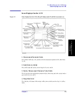
Service mode status
Svc
Indicates that the instrument is in service mode, which is intended for
servicing use only. The accuracy of data measured in this mode is not
guaranteed. For more information, refer to the “Service Manual.”
(blank)
Indicates that the instrument is ready for normal measurement use.
Sweep/trigger status
Hld
Indicates that the sweep function is in Hold status (i.e., not enabled).
To enable the sweep function, you must select one of the available
sweep modes (single-cycle sweep, group sweep, or continuous sweep).
¯
Indicates that the instrument is performing a sweep cycle. This
indicator appears at the measurement point on the trace 1.5 seconds
after the start of a sweep cycle.
ext
Indicates that the instrument is waiting for an external signal that
triggers the start of measurement. This indicator appears after you
have used the keystroke sequence
[Trigger]
-
SOURCE [ ]
-
EXTERNAL
to specify that the trigger signal be input from an external
trigger source (via the external trigger input).
man
Indicates that the instrument is in manual trigger mode, in which you
can manually start measurement by pressing the
MANUAL
key. This
indicator appears after you have used the keystroke sequence
[Trigger]
-
SOURCE [ ]
-
MANUAL
.
bus
Indicates that the instrument is waiting for a measurement trigger
command to be input through GP-IB or from a LAN. This indicator
appears after you have used the keystroke sequence
[Trigger]
-
SOURCE [ ]
-
HP-IB/LAN
.
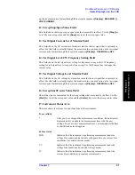
18. Equivalent Circuit Parameters Field
This field shows the equivalent circuit parameter values after you have used the keystroke
sequence
[Display]
-
more 1/2
-
EQUIV CKT
-
PARAMETERS on OFF
. To use this field to
view the parameter values, you can first either apply the equivalent circuit analysis feature
to calculate the parameter values from the trace representing the mesured frequency
characteristics or enter the equivalent parameter values for simulating frequency
characteristics.
19. External Reference Input Status Field
When a reference signal is input to the external reference input terminal on the rear panel,
this field shows “ExtRef” (even if the instrument is not phase locked). The indicator
disappears when the reference signal stops.
20. Parameter Setting/Instrument Message Field
When you press a key to set a particular parameter (for example, the
[Start]
to set the
sweep start value), this field shows the current setting. When you are changing the current
setting, the field also serves as the place to enter the new value through the ENTRY block
keys. In addition, an instrument message such as an error message may appear in the upper
part of this field. For a list of common error messages, Refer to Appendix C , “Error
Содержание 4294A
Страница 1: ......
Страница 2: ......
Страница 4: ......
Страница 5: ......
Страница 6: ......
Страница 8: ......
Страница 16: ...8 ...
Страница 30: ...22 Chapter1 Installation Power Cable Figure 1 2 Alternative Power Cable Options ...
Страница 70: ...62 Chapter3 Front Rear Panel and LCD Display Items Displayed on the LCD ...
Страница 100: ...92 Chapter5 Setting Measurement Conditions Setting Sweep Range Figure 5 7 After MKR CENTER Figure 5 8 ...
Страница 101: ...Chapter 5 93 Setting Measurement Conditions Setting Sweep Range 5 Setting Measurement Conditions Figure 5 9 ...
Страница 106: ...98 Chapter5 Setting Measurement Conditions Setting Number of Points NOP Figure 5 13 Number of points 801 ...
Страница 330: ...322 Chapter9 Setting Using Control and Management Functions Performing Self Diagnosis of the Agilent 4294A ...
Страница 436: ...428 AppendixB Key Definitions Softkeys displayed by pressing the Recall key ...
Страница 454: ...446 AppendixC Error messages WRONG I O PORT DIRECTION ...
Страница 462: ...454 AppendixD Initial Settings Initial Settings Settings that can be Saved Recalled Settings that can be Backed Up ...
Страница 468: ......


