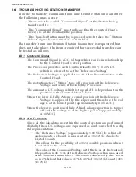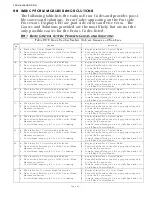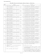
TROUBLESHOOTING
Page B6-3
B6-3 R
EMOTE
S
TATION
S
ELECT
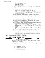
The second required item for taking command is “Station Select” or
depressing of the Transfer Button.
• The Transfer Button can be tested by entering the Diagnostic
Menu H0.
Control Head Lever Position
A/D Count
Ahead Shift Point
537
Full Ahead
821 - 841
Lever Out of Range High
910
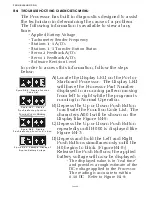
Figure B6-28: Display Station A/D’s No Station
Transfer Button Depressed
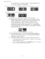
Figure B6-29: Example Display Station A/D’s Transfer
Button Depressed for Stations 1 - 4
Figure B6-30: Display Station A/D/s Transfer Button
Depressed for Station 5
A) Depress the Up or Down (scroll) Push
Button until four zeroes are displayed
without decimal points as shown in Fig-
B) For Stations 1 - 4 when the Transfer
Button is depressed, the
0
which repre-
sents that remote station, will change
to a
1
as shown in Figure B6-29:. For
Station 5 when the Transfer Button is
depressed, all four decimal points will
light as shown in Figure B6-30:
•
Whenever command cannot be gained
at a particular remote station, the Sta-
tion Select and Command Signals are
the first to be investigated. If either
the Command Signal is out of range or
the Station Select is inoperable, com-
mand will not be accepted at that
remote station.
Table B6-3: Control Head Lever A/D Counts
Summary of Contents for ClearCommand 9000 Series
Page 132: ......
Page 133: ...APPENDIX A...
Page 134: ......
Page 139: ......
Page 140: ...Page A 4...
Page 143: ......
Page 144: ...10...
Page 148: ...Page A 18...
Page 149: ...Page A 19 TEMPLATE...
Page 150: ...Page A 20...
Page 152: ...Page A 22...
Page 154: ...Page A 24...
Page 156: ...Page A 26...
Page 157: ...Page A 27 Drawing 11488D 1 Twin Screw Single APS Connection Alternate Remote Switch...
Page 158: ...Page A 28...
Page 159: ...Page A 29 Drawing 11488D 2 Twin Screw Dual APS Connections...
Page 160: ...Page A 30...
Page 161: ...Page A 31 Drawing 11488D 3 APS Notes Page...
Page 162: ...Page A 32...
Page 164: ...Page A 34...
Page 166: ...Page A 36...
Page 170: ...Page A 40...
Page 172: ...Page A 42...
Page 176: ...Page A 46...
Page 178: ...Page C 48 ZF Mathers LLC 12125 Harbour Reach Drive Suite B Mukilteo WA 98275...
Page 179: ...APPENDIX B...
Page 180: ......
Page 234: ...Appendix B 6...
Page 238: ...Appendix B 10...
Page 242: ...Appendix B 14...
Page 247: ...Service Field Test Unit Reference Manual MM13927 Rev E 4 07...
Page 248: ......
Page 250: ...Page ii Table of Contents...
Page 264: ...SERVICE FIELD TEST UNIT MM13927 RvD 10 03 Page 3 2...
Page 265: ...APPENDIX C...
Page 266: ......
Page 267: ...Appendix C 1 Drawing 12284A 1 ClearCommand Diagram all options...
Page 268: ...Appendix C 2...
Page 269: ...Appendix C 3 Drawing 12284A 2 ClearCommand Circuit Board Connections...
Page 270: ...Appendix C 4...
Page 271: ...Appendix C 5 Drawing 12284A 3 ClearCommand Drawing Notes Page...
Page 272: ...Appendix C 6...


