


INSTALLATION
Page4-5
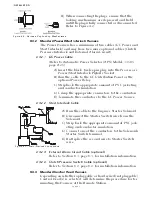
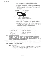
B) Run the cables to the transmission.
C) Plug the DIN connector into the Ahead and Astern Sole-
noids.
D) Plug the DIN connector into the Troll proportional sole-
noid, and if installed the Troll ON/OFF solenoid.
E) If Twin Screw, repeat steps A) thru D) on the opposite
side.
4-4 H
ARD
-W
IRED
C
ABLE
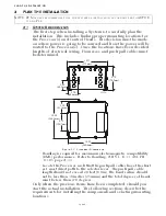
4-4.1 Liquid Tight Connector
4-4.2 Standard Processor Cable Holes
When hard-wiring a Processor or installing additional Station
pigtails, the cables must enter the enclosure through Liquid Tight
Connectors in the appropriate holes as shown in Figure 4-5:.
4-4.3 Standard Circuit Board Connections
On a Standard Processor, in lieu of using Harnesses for Control
Heads, Power, Serial Communication and Tachometer, the Pro-
cessor can be ordered with no pigtails installed. The above con-
nections then must be hard-wired directly to the circuit board
On Standard Processors using pigtails, additional Stations may
also be connected to the Processor by connecting pigtails or hard-
wiring directly to the circuit board.
Refer to Figure 4-6: for specific termination points.
All cables that enter the Enclosure must go through
a Liquid Tight Connector in order to maintain the
moisture resistant integrity of the Processor. These
connectors must be assembled as shown in Figure
4-4:
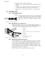
Figure 4-4: Liquid Tight Installation
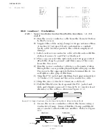
Figure 4-5: Standard Enclosure Cable Holes
1. Station 5
2. Station 3
3. Station 1
4. Alarm, Clutch Pressure, and Start Interlock
5. Power
6. Station 4
7. Station 2
8. Serial Communication
9. Tachometer
Cable
Securing Nut
Grommet
Body
Processor
Enclosure
Nut
12278
Summary of Contents for ClearCommand 9000 Series
Page 132: ......
Page 133: ...APPENDIX A...
Page 134: ......
Page 139: ......
Page 140: ...Page A 4...
Page 143: ......
Page 144: ...10...
Page 148: ...Page A 18...
Page 149: ...Page A 19 TEMPLATE...
Page 150: ...Page A 20...
Page 152: ...Page A 22...
Page 154: ...Page A 24...
Page 156: ...Page A 26...
Page 157: ...Page A 27 Drawing 11488D 1 Twin Screw Single APS Connection Alternate Remote Switch...
Page 158: ...Page A 28...
Page 159: ...Page A 29 Drawing 11488D 2 Twin Screw Dual APS Connections...
Page 160: ...Page A 30...
Page 161: ...Page A 31 Drawing 11488D 3 APS Notes Page...
Page 162: ...Page A 32...
Page 164: ...Page A 34...
Page 166: ...Page A 36...
Page 170: ...Page A 40...
Page 172: ...Page A 42...
Page 176: ...Page A 46...
Page 178: ...Page C 48 ZF Mathers LLC 12125 Harbour Reach Drive Suite B Mukilteo WA 98275...
Page 179: ...APPENDIX B...
Page 180: ......
Page 234: ...Appendix B 6...
Page 238: ...Appendix B 10...
Page 242: ...Appendix B 14...
Page 247: ...Service Field Test Unit Reference Manual MM13927 Rev E 4 07...
Page 248: ......
Page 250: ...Page ii Table of Contents...
Page 264: ...SERVICE FIELD TEST UNIT MM13927 RvD 10 03 Page 3 2...
Page 265: ...APPENDIX C...
Page 266: ......
Page 267: ...Appendix C 1 Drawing 12284A 1 ClearCommand Diagram all options...
Page 268: ...Appendix C 2...
Page 269: ...Appendix C 3 Drawing 12284A 2 ClearCommand Circuit Board Connections...
Page 270: ...Appendix C 4...
Page 271: ...Appendix C 5 Drawing 12284A 3 ClearCommand Drawing Notes Page...
Page 272: ...Appendix C 6...