


INSTALLATION
Page4-1
4
INSTALLATION
4-1 P
ROCESSOR
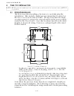
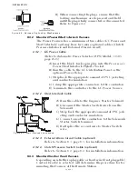
A) Secure the Processor to the mounting surface with three 1/4
inch or M6 fasteners, leaving the fourth fastener unused at this
time.
B) Connect the Processor to the Hull or Bonding Bus by running a
12 AWG or larger wire between the Processor’s fourth mount-
ing fastener and the Bonding Bus. (The Processor is bonded if
mounted directly to a metallic surface that is connected to a
metal hull) (Refer to Bonding: A.B.Y.C. E-11, 46 CFR 111.05,
page A-33)
4-2 C
ONTROL
H
EAD
(
S
)
4-2.1 400, MC2000 and 700 Series Control Heads
Refer to the appropriate Control Head Dimensions and Variations
Service Sheet in Appendix A for installation.
4-2.2 500 Series Control Heads
Refer to the Installation Manual supplied with the 500 Series
Control Head Assembly for installation instructions.
4-2.3 Handheld Remote Controls
Refer to the Installation Manual supplied with the Handheld
Remote for installation instructions.
4-3 W
IRE
H
ARNESS
I
NSTALLATION
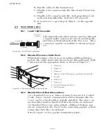
The standard Off-the-Shelf Processor has five Pigtails with plugs on the
ends. Two of the plugs are for Remote Stations and one each for Power/
Start Interlock, Serial Communication, and Tach Sensor. Additional
Harnesses required will depend on the actual installation. Four differ-
ent styles of plugs are utilized but are inserted in an identical fashion as
follows:
4-3.1 Plug Insertion and Extraction
NOTE: B
EFORE
STARTING
THE
ACTUAL
INSTALLATION
OF
THE
C
ONTROL
S
YSTEM
,
MAKE
SURE
YOU
HAVE
THE
CORRECT
PARTS
AND
TOOLS
ON
HAND
. S
EE
S
ECTION
3. R
EAD
ALL
THE
INSTRUC
-
TIONS
PERTINENT
TO
EACH
PART
BEFORE
BEGINNING
THE
INSTALLATION
OF
THE
PART
.
CAUTION: Static electricity can destroy electronic components. Connect the wrist
strap provided, to the Processor frame whenever working on the Processor
with the enclosure cover open. This will drain any static charge you may
have on your person.
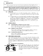
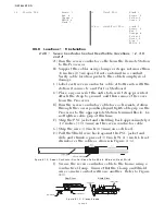
A) Prior to inserting the plug, pay close attention to
the number of pins and the keying of the plug.
The plug is designed to be inserted one way
only, but can be forced together in the opposite
orientation. Refer to Figure 4-1: to insert plug
correctly.
Figure 4-1: Harness Plug Keying
Processor Pigtail
Harness Connector
Summary of Contents for ClearCommand 9000 Series
Page 132: ......
Page 133: ...APPENDIX A...
Page 134: ......
Page 139: ......
Page 140: ...Page A 4...
Page 143: ......
Page 144: ...10...
Page 148: ...Page A 18...
Page 149: ...Page A 19 TEMPLATE...
Page 150: ...Page A 20...
Page 152: ...Page A 22...
Page 154: ...Page A 24...
Page 156: ...Page A 26...
Page 157: ...Page A 27 Drawing 11488D 1 Twin Screw Single APS Connection Alternate Remote Switch...
Page 158: ...Page A 28...
Page 159: ...Page A 29 Drawing 11488D 2 Twin Screw Dual APS Connections...
Page 160: ...Page A 30...
Page 161: ...Page A 31 Drawing 11488D 3 APS Notes Page...
Page 162: ...Page A 32...
Page 164: ...Page A 34...
Page 166: ...Page A 36...
Page 170: ...Page A 40...
Page 172: ...Page A 42...
Page 176: ...Page A 46...
Page 178: ...Page C 48 ZF Mathers LLC 12125 Harbour Reach Drive Suite B Mukilteo WA 98275...
Page 179: ...APPENDIX B...
Page 180: ......
Page 234: ...Appendix B 6...
Page 238: ...Appendix B 10...
Page 242: ...Appendix B 14...
Page 247: ...Service Field Test Unit Reference Manual MM13927 Rev E 4 07...
Page 248: ......
Page 250: ...Page ii Table of Contents...
Page 264: ...SERVICE FIELD TEST UNIT MM13927 RvD 10 03 Page 3 2...
Page 265: ...APPENDIX C...
Page 266: ......
Page 267: ...Appendix C 1 Drawing 12284A 1 ClearCommand Diagram all options...
Page 268: ...Appendix C 2...
Page 269: ...Appendix C 3 Drawing 12284A 2 ClearCommand Circuit Board Connections...
Page 270: ...Appendix C 4...
Page 271: ...Appendix C 5 Drawing 12284A 3 ClearCommand Drawing Notes Page...
Page 272: ...Appendix C 6...