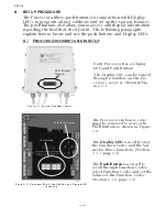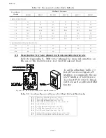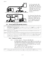
SET UP
Page5-3
•
While in Set Up Mode, deactivates Set Up Mode, saves the
displayed Value to memory and returns to the Function
Menu. (must hold the button until the blinking stops)
5-1.2.3 Left Push Button Only
Pressing the Left Push Button once has the following func-
tions:
• Deactivates Set Up Mode without any changes to the
Value being stored to memory. The Left Push Button must
be held down until function code stops blinking. The
default value will then be displayed.
5-1.2.4 Right Push Button Only
Pressing the Right Push Button once has the following
functions:
5-2 A
CTIVATING
S
ET
U
P
M
ODE
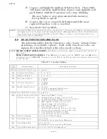
A) The Display LED is in Normal operating condition with the red
running Processor Part Number.
B) Depressing either the Up or Down Push Button will activate the
Function Menu.
C) Depressing the Up or Down Push Button will scroll through the
Function Codes one at a time.
D) Once the desired Function Code is visible on the Display LED,
press and hold down the Left and Right Push Buttons simulta-
neously, until the Function Code begins to blink.
E) Depressing the Up Push Button will increase the Value of the
Function, while pressing the Down Push Button will decrease
the Value of the Function. (Pressing and holding the Up or
Down Push Button will increase or decrease the Value rapidly)
5-3 S
TORING
V
ALUES
T
O
M
EMORY
Once the desired Value has been reached in Set Up Mode, the
Value is stored to memory as follows:
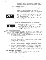
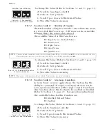
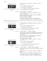
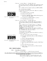
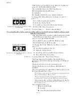
Figure 5-6: Display LED Error
Menu Example
• While in Function Menu, changes the Display LED to the
Error Menu, if any errors are present. (has no effect if
there are no errors stored)
• While in the Error Menu, changes the Display LED back to
the Function Menu.
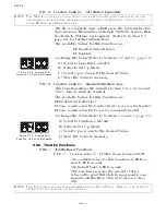
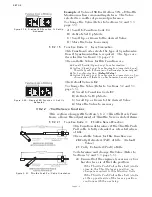
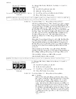
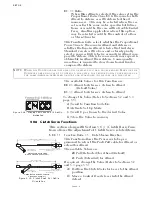
Figure 5-7: Display LED Four Digit
Value
• While in the Error Menu, clears inactive errors. (Active
errors blink, inactive do not)
• While in Set Up Mode or Function Menu, allows the
Value of the current Function Code to be displayed
with all four Display LEDs.
NOTE: T
O
E
SCAPE
FROM
THE
S
ET
U
P
PROCEDURE
AT
ANY
TIME
WITHOUT
SAVING
THE
CHANGED
VALUE
TO
MEMORY
,
DEPRESS
THE
L
EFT
P
USH
B
UTTON
. T
HE
F
UNCTION
C
ODE
WILL
STOP
FLASHING
AND
THE
F
UNCTION
WILL
BE
SAVED
WITH
THE
ORIGINAL
V
ALUE
.
Summary of Contents for ClearCommand 9000 Series
Page 132: ......
Page 133: ...APPENDIX A...
Page 134: ......
Page 139: ......
Page 140: ...Page A 4...
Page 143: ......
Page 144: ...10...
Page 148: ...Page A 18...
Page 149: ...Page A 19 TEMPLATE...
Page 150: ...Page A 20...
Page 152: ...Page A 22...
Page 154: ...Page A 24...
Page 156: ...Page A 26...
Page 157: ...Page A 27 Drawing 11488D 1 Twin Screw Single APS Connection Alternate Remote Switch...
Page 158: ...Page A 28...
Page 159: ...Page A 29 Drawing 11488D 2 Twin Screw Dual APS Connections...
Page 160: ...Page A 30...
Page 161: ...Page A 31 Drawing 11488D 3 APS Notes Page...
Page 162: ...Page A 32...
Page 164: ...Page A 34...
Page 166: ...Page A 36...
Page 170: ...Page A 40...
Page 172: ...Page A 42...
Page 176: ...Page A 46...
Page 178: ...Page C 48 ZF Mathers LLC 12125 Harbour Reach Drive Suite B Mukilteo WA 98275...
Page 179: ...APPENDIX B...
Page 180: ......
Page 234: ...Appendix B 6...
Page 238: ...Appendix B 10...
Page 242: ...Appendix B 14...
Page 247: ...Service Field Test Unit Reference Manual MM13927 Rev E 4 07...
Page 248: ......
Page 250: ...Page ii Table of Contents...
Page 264: ...SERVICE FIELD TEST UNIT MM13927 RvD 10 03 Page 3 2...
Page 265: ...APPENDIX C...
Page 266: ......
Page 267: ...Appendix C 1 Drawing 12284A 1 ClearCommand Diagram all options...
Page 268: ...Appendix C 2...
Page 269: ...Appendix C 3 Drawing 12284A 2 ClearCommand Circuit Board Connections...
Page 270: ...Appendix C 4...
Page 271: ...Appendix C 5 Drawing 12284A 3 ClearCommand Drawing Notes Page...
Page 272: ...Appendix C 6...


