


INSTALLATION
Page4-2
4-3.2 Standard Power/Start Interlock Harness
The Power Harness has a minimum of two cables (DC Power and
Start Interlock) and may have two more optional cables (Clutch
Pressure Interlock and External Alarm Circuit).
4-3.2.1 DC Power Cable
(Refer to Automatic Power Selector (APS) Model: 13505,
page A-25)
A) Insert the black, twelve pin plug into the Processor’s
Power/Start Interlock Pigtail’s Socket.
B) Run the cable to the DC Distribution Panel or the
optional Power Relay.
C) Strip back the appropriate amount of PVC jacketing
and conductor insulation.
D) Crimp the appropriate connectors to the conductors.
E) Terminate the conductors to the DC Power Source.
4-3.2.2 Start Interlock Cable
4-3.2.3 External Alarm Circuit Cable (optional)
Refer to Section 8-1, page 8-1, for installation information.
4-3.2.4 Clutch Pressure Switch Cable (optional)
Refer to Section 8-2, page 8-2, for installation information.
4-3.3 Standard Control Head Harness
Depending on whether a pluggable or hard-wired (not pluggable)
Control Head(s) is selected, will determine the procedure for ter-
minating the Harness at the Remote Station.
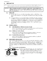
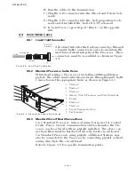
B) When connecting the plugs, ensure that the
locking mechanisms are depressed and held
until the plug is fully connected or disconnected.
Refer to Figure 4-2:
Figure 4-2: Harness Plug Locking Mechanisms
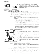
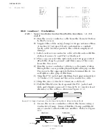
Figure 4-3: Start Interlock Connections
A) Run the cable to the Engine’s Starter Solenoid.
B) Disconnect the Starter Switch wire from the
Solenoid.
C) Strip back the appropriate amount of PVC jack-
eting and conductor insulation.
D) Connect one of the conductors to the Solenoid’s
Starter Switch terminal.
E) Butt splice the second wire to Starter Switch
wire.
Summary of Contents for ClearCommand 9000 Series
Page 132: ......
Page 133: ...APPENDIX A...
Page 134: ......
Page 139: ......
Page 140: ...Page A 4...
Page 143: ......
Page 144: ...10...
Page 148: ...Page A 18...
Page 149: ...Page A 19 TEMPLATE...
Page 150: ...Page A 20...
Page 152: ...Page A 22...
Page 154: ...Page A 24...
Page 156: ...Page A 26...
Page 157: ...Page A 27 Drawing 11488D 1 Twin Screw Single APS Connection Alternate Remote Switch...
Page 158: ...Page A 28...
Page 159: ...Page A 29 Drawing 11488D 2 Twin Screw Dual APS Connections...
Page 160: ...Page A 30...
Page 161: ...Page A 31 Drawing 11488D 3 APS Notes Page...
Page 162: ...Page A 32...
Page 164: ...Page A 34...
Page 166: ...Page A 36...
Page 170: ...Page A 40...
Page 172: ...Page A 42...
Page 176: ...Page A 46...
Page 178: ...Page C 48 ZF Mathers LLC 12125 Harbour Reach Drive Suite B Mukilteo WA 98275...
Page 179: ...APPENDIX B...
Page 180: ......
Page 234: ...Appendix B 6...
Page 238: ...Appendix B 10...
Page 242: ...Appendix B 14...
Page 247: ...Service Field Test Unit Reference Manual MM13927 Rev E 4 07...
Page 248: ......
Page 250: ...Page ii Table of Contents...
Page 264: ...SERVICE FIELD TEST UNIT MM13927 RvD 10 03 Page 3 2...
Page 265: ...APPENDIX C...
Page 266: ......
Page 267: ...Appendix C 1 Drawing 12284A 1 ClearCommand Diagram all options...
Page 268: ...Appendix C 2...
Page 269: ...Appendix C 3 Drawing 12284A 2 ClearCommand Circuit Board Connections...
Page 270: ...Appendix C 4...
Page 271: ...Appendix C 5 Drawing 12284A 3 ClearCommand Drawing Notes Page...
Page 272: ...Appendix C 6...