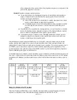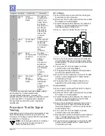
The following test procedure covers the 2 items included in the Qualitative Failure Analysis; 1)
Control Head Potentiometer failure, and 2) Loss of power supply.
1)
Failure: Control Head Potentiometer failure
.
a)
Results: The Processor will shift to Neutral (if needed) and throttle will go to Idle, (if
needed).
b)
Test Procedure
i)
Turn power on to both Port and Starboard Processors. Take command at a Control
Head.
ii)
Move the Port and Starboard Control Head levers to approximately ½ Ahead.
iii)
Locate the green wire coming from the Port Control Head in command, connecting to
pin 6 of the respective terminal block on the ClearCommand 9000 Series circuit board.
Disconnect it from the ClearCommand 9000 Series circuit board.
(1)
The Port Processor will shift to Neutral and throttle will go to Idle.
(2)
The Port Control Head will give an alarm tone indicating a faulty potentiometer.
iv)
Move the Port and Starboard Control Head levers back to Neutral. Reconnect the
green wire.
v)
Repeat for Starboard side.
2)
Failure: Power failure to
ClearCommand 9000 Series
(A power failure to the ClearCommand 9000 Series circuit board will have the same
results as a failed microprocessor)
a)
Results
i)
Throttle signal to Idle and clutch servo will remain at last commanded position.
ii)
LED at Control Heads will not be lit.
iii)
Opposite engine still under power has full control.
b)
Test Procedure.
i)
Turn power on to both Port and Starboard Processors. Take command at a Control
Head.
ii)
Move the Port and Starboard Control Head levers to approximately ½ Ahead.
iii)
Turn power off to the Port side only.
(1)
Port side will go to Idle and clutch servo will remain at last commanded position.
(2)
LED on the Port side of the Control Head in command will go off.
(3)
The Port Control Head will no longer have command of the engine and gear.
(4)
The Starboard Control Head will still have full command of the Starboard engine
and gear.
iv)
Turn power on to the Port Processor. Take command of the Port side.
(1)
The Port Control Head will operate as usual-(Non-volatile memory)
v)
Repeat test for Starboard Processor.
Summary of Contents for ClearCommand 9000 Series
Page 132: ......
Page 133: ...APPENDIX A...
Page 134: ......
Page 139: ......
Page 140: ...Page A 4...
Page 143: ......
Page 144: ...10...
Page 148: ...Page A 18...
Page 149: ...Page A 19 TEMPLATE...
Page 150: ...Page A 20...
Page 152: ...Page A 22...
Page 154: ...Page A 24...
Page 156: ...Page A 26...
Page 157: ...Page A 27 Drawing 11488D 1 Twin Screw Single APS Connection Alternate Remote Switch...
Page 158: ...Page A 28...
Page 159: ...Page A 29 Drawing 11488D 2 Twin Screw Dual APS Connections...
Page 160: ...Page A 30...
Page 161: ...Page A 31 Drawing 11488D 3 APS Notes Page...
Page 162: ...Page A 32...
Page 164: ...Page A 34...
Page 166: ...Page A 36...
Page 170: ...Page A 40...
Page 172: ...Page A 42...
Page 176: ...Page A 46...
Page 178: ...Page C 48 ZF Mathers LLC 12125 Harbour Reach Drive Suite B Mukilteo WA 98275...
Page 179: ...APPENDIX B...
Page 180: ......
Page 234: ...Appendix B 6...
Page 238: ...Appendix B 10...
Page 242: ...Appendix B 14...
Page 247: ...Service Field Test Unit Reference Manual MM13927 Rev E 4 07...
Page 248: ......
Page 250: ...Page ii Table of Contents...
Page 264: ...SERVICE FIELD TEST UNIT MM13927 RvD 10 03 Page 3 2...
Page 265: ...APPENDIX C...
Page 266: ......
Page 267: ...Appendix C 1 Drawing 12284A 1 ClearCommand Diagram all options...
Page 268: ...Appendix C 2...
Page 269: ...Appendix C 3 Drawing 12284A 2 ClearCommand Circuit Board Connections...
Page 270: ...Appendix C 4...
Page 271: ...Appendix C 5 Drawing 12284A 3 ClearCommand Drawing Notes Page...
Page 272: ...Appendix C 6...

