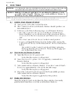


SEA TRIALS
Page7-5
•
Once the engine RPM’s are within 1% of one another, the green
LED will remain solidly lit.
C) Check the engine tachometers to see if they are within 1% of
one another.
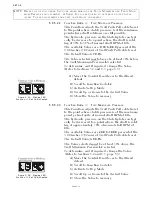
D) Move both Control Head levers side by side to approximately
50% of the Throttle range.
E) Check the engine tachometers to see if they are within 1% of
one another.
F) Move both Control Head levers side by side to approximately
75% of the Throttle range.
G) Check the engine tachometers to see if they are within 1% of
one another.
H) Move both Control Head levers side by side to 100% of the
Throttle range.
I) Check the engine tachometers to see if they are within 1% of
one another.
While synchronized, if the tachometers have a greater than 1%
percent difference at any engine RPM, or if they appear to be
continually “hunting” for the correct RPM, refer to the Appendix
B, B9 Troubleshooting Section.
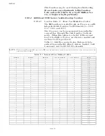
7-15 T
ROLLING
V
ALVE
A
DJUSTMENTS
7-15.1 Integrated Servo Trolling
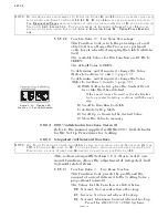
7-15.1.1 Enabling Troll
Press and hold the Transfer Button for two seconds with
the Control Head lever in the Neutral detent.
• The Control Head’s red LED should begin blinking rap-
idly, indicating that Troll is enabled.
• If not, refer to Section 5-6.4.1.4, page 5-29, Function
Code L0 – Troll Enable and Control Head Lever Troll
Range.
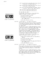
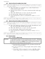
7-15.1.2 Troll Minimum Pressure Adjustments (Function Code L2)
A) The red LED should still be blinking rapidly. If not,
enable troll.
B) If connected, disconnect the Troll push-pull cable from
the Troll selector lever.
C) Move the Control Head lever to the Ahead detent.
NOTE: D
O
NOT
ATTEMPT
THE
FOLLOWING
ADJUSTMENTS
UNTIL
THE
G
EAR
O
IL
TEMPERATURE
HAS
REACHED
A
MINIMUM
OF
140
DEGREES
F (60
DEGREES
C).
Summary of Contents for ClearCommand 9000 Series
Page 132: ......
Page 133: ...APPENDIX A...
Page 134: ......
Page 139: ......
Page 140: ...Page A 4...
Page 143: ......
Page 144: ...10...
Page 148: ...Page A 18...
Page 149: ...Page A 19 TEMPLATE...
Page 150: ...Page A 20...
Page 152: ...Page A 22...
Page 154: ...Page A 24...
Page 156: ...Page A 26...
Page 157: ...Page A 27 Drawing 11488D 1 Twin Screw Single APS Connection Alternate Remote Switch...
Page 158: ...Page A 28...
Page 159: ...Page A 29 Drawing 11488D 2 Twin Screw Dual APS Connections...
Page 160: ...Page A 30...
Page 161: ...Page A 31 Drawing 11488D 3 APS Notes Page...
Page 162: ...Page A 32...
Page 164: ...Page A 34...
Page 166: ...Page A 36...
Page 170: ...Page A 40...
Page 172: ...Page A 42...
Page 176: ...Page A 46...
Page 178: ...Page C 48 ZF Mathers LLC 12125 Harbour Reach Drive Suite B Mukilteo WA 98275...
Page 179: ...APPENDIX B...
Page 180: ......
Page 234: ...Appendix B 6...
Page 238: ...Appendix B 10...
Page 242: ...Appendix B 14...
Page 247: ...Service Field Test Unit Reference Manual MM13927 Rev E 4 07...
Page 248: ......
Page 250: ...Page ii Table of Contents...
Page 264: ...SERVICE FIELD TEST UNIT MM13927 RvD 10 03 Page 3 2...
Page 265: ...APPENDIX C...
Page 266: ......
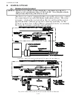
Page 267: ...Appendix C 1 Drawing 12284A 1 ClearCommand Diagram all options...
Page 268: ...Appendix C 2...
Page 269: ...Appendix C 3 Drawing 12284A 2 ClearCommand Circuit Board Connections...
Page 270: ...Appendix C 4...
Page 271: ...Appendix C 5 Drawing 12284A 3 ClearCommand Drawing Notes Page...
Page 272: ...Appendix C 6...