INTRODUCTION
Page 1-6
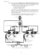
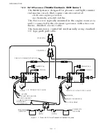
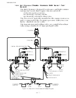
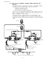
1-2.5 9221 Processor
(Throttle - Electronic, Shift - Solenoid, Troll -
Servo 2)
The 9221
System is designed for pleasure and light commer-
cial marine vessels that require remote control of:
• electronic engine governors
• solenoid activated clutches
• mechanically actuated trolling valves
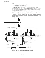
The Processor is typically mounted in the engine room area
and is connected to the electronic governor with a two-con-
ductor, shielded, electric cable.
The transmission’s Ahead and Astern solenoids are con-
nected via 2 two-conductor cables, and the trolling valve is
controlled mechanically using a standard 33C type push-pull
cable.
Figure 1-5: Basic 9221 ClearCommand System Diagram
33C PUSH/PULL CABLE
STBD
STATION 2
STATION 1
PORT
12297A
SERIAL COMMUNICATION
10 AMP CIRCUIT
BREAKERS
(BY OTHERS)
APS
CLUTCH PRES.
START INTERLOCK
ALARM
START INTERLOCK
CLUTCH PRES.
ALARM
TACH 1
TACH 1
THROTTLE
THROTTLE
TROLL
MAX
SLIP
MIN
SLIP
TROLL
33C PUSH/PULL CABLE
30A
FUSE
-
+
-
+
GROUND
COMMON
GROUND
COMMON
AHEAD/
ASTERN
AHEAD/
ASTERN
MAX
SLIP
MIN
SLIP
30A
FUSE
Summary of Contents for ClearCommand 9000 Series
Page 132: ......
Page 133: ...APPENDIX A...
Page 134: ......
Page 139: ......
Page 140: ...Page A 4...
Page 143: ......
Page 144: ...10...
Page 148: ...Page A 18...
Page 149: ...Page A 19 TEMPLATE...
Page 150: ...Page A 20...
Page 152: ...Page A 22...
Page 154: ...Page A 24...
Page 156: ...Page A 26...
Page 157: ...Page A 27 Drawing 11488D 1 Twin Screw Single APS Connection Alternate Remote Switch...
Page 158: ...Page A 28...
Page 159: ...Page A 29 Drawing 11488D 2 Twin Screw Dual APS Connections...
Page 160: ...Page A 30...
Page 161: ...Page A 31 Drawing 11488D 3 APS Notes Page...
Page 162: ...Page A 32...
Page 164: ...Page A 34...
Page 166: ...Page A 36...
Page 170: ...Page A 40...
Page 172: ...Page A 42...
Page 176: ...Page A 46...
Page 178: ...Page C 48 ZF Mathers LLC 12125 Harbour Reach Drive Suite B Mukilteo WA 98275...
Page 179: ...APPENDIX B...
Page 180: ......
Page 234: ...Appendix B 6...
Page 238: ...Appendix B 10...
Page 242: ...Appendix B 14...
Page 247: ...Service Field Test Unit Reference Manual MM13927 Rev E 4 07...
Page 248: ......
Page 250: ...Page ii Table of Contents...
Page 264: ...SERVICE FIELD TEST UNIT MM13927 RvD 10 03 Page 3 2...
Page 265: ...APPENDIX C...
Page 266: ......
Page 267: ...Appendix C 1 Drawing 12284A 1 ClearCommand Diagram all options...
Page 268: ...Appendix C 2...
Page 269: ...Appendix C 3 Drawing 12284A 2 ClearCommand Circuit Board Connections...
Page 270: ...Appendix C 4...
Page 271: ...Appendix C 5 Drawing 12284A 3 ClearCommand Drawing Notes Page...
Page 272: ...Appendix C 6...

