


INSTALLATION
Page4-16
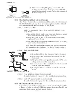
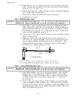
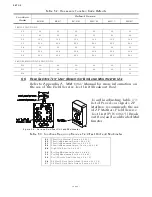
4-4.7.2.4 Plug Termination
A) Strip back 2 1/4 inches (57,15mm) of PVC jacket-
ing.
B) Slide the boot onto the cable.
C) Strip back 1/4 inch (6,35mm) from the eight con-
ductors.
D) Crimp Pins onto the eight conductors.
E) Insert the pins into the appropriate terminations
as shown in Table 4-6:.
F) Slide the boot over the connector.
G) Tie-wrap the boot in place.
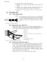
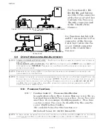
4-4.8 Locations 10 Installation
4-4.8.1 Clutch Cable (Location 10)
A single four-conductor cable must connect the two Shift
cables to the Processor through a 12 pin plug.
4-4.8.1.1 Processor Termination
A) Install a liquid tight connector into hole no.10.
B) Run a 32 inch (0,82m) piece of four-conductor
cable through the liquid tight connector and
tighten, leaving 16 inches (0,41m) outside of the
Processor.
C) Strip back 4 inches (101,6mm) of the PVC jacket
inside the Processor.
Figure 4-23: Clutch Cable Plug Termination Connections
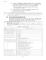
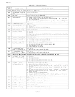
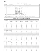
Table 4-6: Clutch/Troll Termination Table
Description
Conductor Color
Processor Termination
Plug Termination
Ahead Clutch Solenoid (+)
Brown
TB11-2
Pin 3
Ahead Clutch Solenoid (-)
Green
TB11-6
Pin 4
Astern Clutch Solenoid (+)
Black
TB11-1
Pin 5
Astern Clutch Solenoid (-)
Yellow
TB11-5
Pin 6
Troll On/Off Solenoid (+)
Orange
TB11-4
Pin 9
Troll On/Off Solenoid (-)
White
TB11-8
Pin 10
Troll Proportional Solenoid (+)
Red
TB11-3
Pin 11
Troll Proportional Solenoid (-)
Blue
TB11-7
Pin 12
Summary of Contents for ClearCommand 9000 Series
Page 132: ......
Page 133: ...APPENDIX A...
Page 134: ......
Page 139: ......
Page 140: ...Page A 4...
Page 143: ......
Page 144: ...10...
Page 148: ...Page A 18...
Page 149: ...Page A 19 TEMPLATE...
Page 150: ...Page A 20...
Page 152: ...Page A 22...
Page 154: ...Page A 24...
Page 156: ...Page A 26...
Page 157: ...Page A 27 Drawing 11488D 1 Twin Screw Single APS Connection Alternate Remote Switch...
Page 158: ...Page A 28...
Page 159: ...Page A 29 Drawing 11488D 2 Twin Screw Dual APS Connections...
Page 160: ...Page A 30...
Page 161: ...Page A 31 Drawing 11488D 3 APS Notes Page...
Page 162: ...Page A 32...
Page 164: ...Page A 34...
Page 166: ...Page A 36...
Page 170: ...Page A 40...
Page 172: ...Page A 42...
Page 176: ...Page A 46...
Page 178: ...Page C 48 ZF Mathers LLC 12125 Harbour Reach Drive Suite B Mukilteo WA 98275...
Page 179: ...APPENDIX B...
Page 180: ......
Page 234: ...Appendix B 6...
Page 238: ...Appendix B 10...
Page 242: ...Appendix B 14...
Page 247: ...Service Field Test Unit Reference Manual MM13927 Rev E 4 07...
Page 248: ......
Page 250: ...Page ii Table of Contents...
Page 264: ...SERVICE FIELD TEST UNIT MM13927 RvD 10 03 Page 3 2...
Page 265: ...APPENDIX C...
Page 266: ......
Page 267: ...Appendix C 1 Drawing 12284A 1 ClearCommand Diagram all options...
Page 268: ...Appendix C 2...
Page 269: ...Appendix C 3 Drawing 12284A 2 ClearCommand Circuit Board Connections...
Page 270: ...Appendix C 4...
Page 271: ...Appendix C 5 Drawing 12284A 3 ClearCommand Drawing Notes Page...
Page 272: ...Appendix C 6...