TROUBLESHOOTING
Page B11-4
B11-3E
LECTRONIC
E
QUAL
T
HROTTLE
S
YNCHRONIZATION
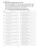
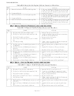
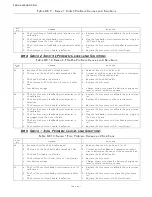
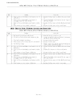
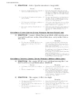
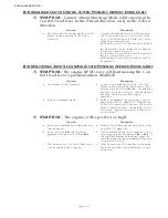
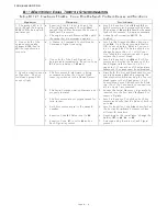
Table B11-21: Electronic Throttle - Equal Throttle Synch Problem Causes and Solutions
System
Causes
Solutions
1. The green LED is lit
solid, though the Engine
RPM’s differ by a signifi-
cant amount.
a. Function Code E7 is set to 00 and the
Throttle Minimum and Throttle Maxi-
mum VAlues differ between the Port and
Starboard Processors.
a. Scroll to Function Codes
E2
and
E3
on
both Processors and compare the Values.
The Values of
E2
and
E3
must be the same
for both Processors. Adjust as necessary.
b. The engines run at different RPM’s with
the same throttle command signals.
b. Active Synchronization MUST be
Enabled.
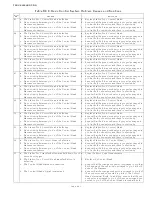
2. One or both of the
engines continually
changes RPM (hunts).
Will not synchronize
properly
a. A Station-in-Command Control Head’s
Command Signal is varying.
a. Scroll to the Diagnostic Menu Function
Code
H0
. Go to the appropriate Station
A/D Count’s display. Refer to Section 5-
6.5.1.1, page 5-40. The Value should not
change by more than +/- 1 A/D Count.
If so, check the connections and if good,
replace the Control Head.
B
.
One or both of the Tach Signals isn’t
being read intermittently. Function Code
E7
is set to a Value of
01 or
03
.
b. Scroll to Function Code
H0
on both Pro-
cessors and display the frequency of the
Tach Signal (refer to Section 5-6.5.1.1,
page 5-40). If variations of the signal are
measured, the cause must be determined
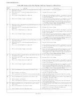
3. Synchronization does
not function. The Con-
trol Head’s green LED
does not light.
a. The Processors think Astern is being
commended when the Control Head
lever is positioned to the Ahead Detent.
a. Place both the Port and Starboard Proces-
sor into Warm-up Mode by pressing the
Transfer Button while moving the Control
Head levers to the Ahead detent. Both
Control Head’s red LEDs should be blink-
ing. If not, the 7-conductor’s connections
at pins 5 and 7 are reversed.
b. The Serial Communication Harness is not
properly installed.
b. Ensure the Serial Harness’ plugs are fully
inserted into the Port and Starboard Pro-
cessor’s Pigtails.
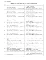
c. The Processors are not programmed for
twin screw.
c. Scroll to Function Code
A1
on both Pro-
cessors and verify that the Value of both is
set to
02
.
d. Both Processors are set to the same ID
number.
d. Scroll to Function Code
A0
and verify that
the Port and Starboard Processors have
different ID numbers.
e. Function Code
E7
Value is set to
02
.
e. Depending on the installation, change the
Value of
E7
to
00
,
01
, or
03
.
f. Function Code
E7
is set to
03
and no
Tach Signal is present.
f. Determine why there is no Tach Signal
present.
Summary of Contents for ClearCommand 9000 Series
Page 132: ......
Page 133: ...APPENDIX A...
Page 134: ......
Page 139: ......
Page 140: ...Page A 4...
Page 143: ......
Page 144: ...10...
Page 148: ...Page A 18...
Page 149: ...Page A 19 TEMPLATE...
Page 150: ...Page A 20...
Page 152: ...Page A 22...
Page 154: ...Page A 24...
Page 156: ...Page A 26...
Page 157: ...Page A 27 Drawing 11488D 1 Twin Screw Single APS Connection Alternate Remote Switch...
Page 158: ...Page A 28...
Page 159: ...Page A 29 Drawing 11488D 2 Twin Screw Dual APS Connections...
Page 160: ...Page A 30...
Page 161: ...Page A 31 Drawing 11488D 3 APS Notes Page...
Page 162: ...Page A 32...
Page 164: ...Page A 34...
Page 166: ...Page A 36...
Page 170: ...Page A 40...
Page 172: ...Page A 42...
Page 176: ...Page A 46...
Page 178: ...Page C 48 ZF Mathers LLC 12125 Harbour Reach Drive Suite B Mukilteo WA 98275...
Page 179: ...APPENDIX B...
Page 180: ......
Page 234: ...Appendix B 6...
Page 238: ...Appendix B 10...
Page 242: ...Appendix B 14...
Page 247: ...Service Field Test Unit Reference Manual MM13927 Rev E 4 07...
Page 248: ......
Page 250: ...Page ii Table of Contents...
Page 264: ...SERVICE FIELD TEST UNIT MM13927 RvD 10 03 Page 3 2...
Page 265: ...APPENDIX C...
Page 266: ......
Page 267: ...Appendix C 1 Drawing 12284A 1 ClearCommand Diagram all options...
Page 268: ...Appendix C 2...
Page 269: ...Appendix C 3 Drawing 12284A 2 ClearCommand Circuit Board Connections...
Page 270: ...Appendix C 4...
Page 271: ...Appendix C 5 Drawing 12284A 3 ClearCommand Drawing Notes Page...
Page 272: ...Appendix C 6...

