


INSTALLATION
Page4-19
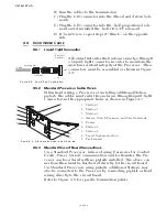
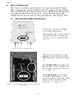
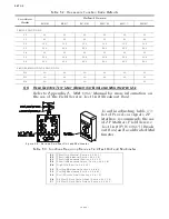
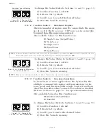
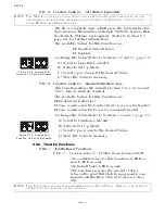
B) Remove one screw from each Cable Anchor Clip and loosen
the other screw. Swing the two Clips clear. Refer to Figure 4-
27:.
C) Insert the appropriate push-pull cable into the Processor
according to the labels located above the cable clips on the
Processor enclosure.
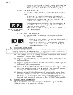
D) When the push-pull cable end is visible within the Processor
interior, reinstall the #10-32 jam nut.
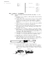
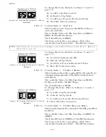
E) Connect the push-pull cables to the hex nuts (See Figure 4-
28:). Use a 7/16 inch socket to turn the hex nut onto the cable
rod end until there is approximately 5/16 inch (7,9mm) of
thread showing beyond the jam nut.
F) Use a 7/16 inch socket wrench and a 5/16-inch open end
wrench to tighten the jam nuts.
G) Position the Cable Anchor Clips to secure the cables to the
Processor housing.
H) Install the screws removed in step B).
I) Tighten all Cable Anchor Clip screws.
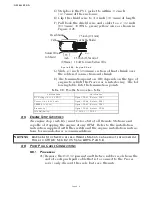
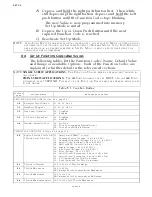
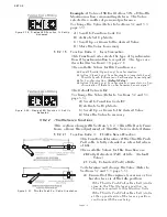
4-6.2 Throttle Selector Lever
A) Ensure that the Throttle push-pull cable and the engine’s
throttle lever are in close proximity to one another at Idle. If
so, proceed to step C) and if not continue with step B).
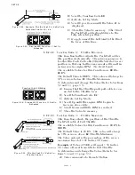
Figure 4-27: Processor Cable Clamp Rotation
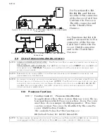
Figure 4-28: Push-Pull Cable Interior Connection
Figure 4-29: Throttle Push-Pull Idle Orientation to Selector Lever
Push-Pull Cable
Jam Nut
Snap Ring
Lead Screw
Lead Screw
Cross-bar
5/16 inch
(7,9mm)
7/16 inch (11,11mm)
Hex Nut
12280
Throttle Selector
Lever at IDLE
Processor Push-Pull Cable Fully Extended
(Default Setting)
12267
8 7/8 inch Maximum
(225,3mm)
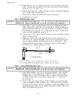
ORIENTATION DOES NOT MATCH
CHANGE FUNCTION E0
Throttle Selector
Lever at IDLE
Processor Push-Pull Cable Fully Extended
(Default Setting)
12267
8 7/8 inch Maximum
(225,3mm)
ORIENTATION MATCHES
DO NOT CHANGE FUNCTION E0
Summary of Contents for ClearCommand 9000 Series
Page 132: ......
Page 133: ...APPENDIX A...
Page 134: ......
Page 139: ......
Page 140: ...Page A 4...
Page 143: ......
Page 144: ...10...
Page 148: ...Page A 18...
Page 149: ...Page A 19 TEMPLATE...
Page 150: ...Page A 20...
Page 152: ...Page A 22...
Page 154: ...Page A 24...
Page 156: ...Page A 26...
Page 157: ...Page A 27 Drawing 11488D 1 Twin Screw Single APS Connection Alternate Remote Switch...
Page 158: ...Page A 28...
Page 159: ...Page A 29 Drawing 11488D 2 Twin Screw Dual APS Connections...
Page 160: ...Page A 30...
Page 161: ...Page A 31 Drawing 11488D 3 APS Notes Page...
Page 162: ...Page A 32...
Page 164: ...Page A 34...
Page 166: ...Page A 36...
Page 170: ...Page A 40...
Page 172: ...Page A 42...
Page 176: ...Page A 46...
Page 178: ...Page C 48 ZF Mathers LLC 12125 Harbour Reach Drive Suite B Mukilteo WA 98275...
Page 179: ...APPENDIX B...
Page 180: ......
Page 234: ...Appendix B 6...
Page 238: ...Appendix B 10...
Page 242: ...Appendix B 14...
Page 247: ...Service Field Test Unit Reference Manual MM13927 Rev E 4 07...
Page 248: ......
Page 250: ...Page ii Table of Contents...
Page 264: ...SERVICE FIELD TEST UNIT MM13927 RvD 10 03 Page 3 2...
Page 265: ...APPENDIX C...
Page 266: ......
Page 267: ...Appendix C 1 Drawing 12284A 1 ClearCommand Diagram all options...
Page 268: ...Appendix C 2...
Page 269: ...Appendix C 3 Drawing 12284A 2 ClearCommand Circuit Board Connections...
Page 270: ...Appendix C 4...
Page 271: ...Appendix C 5 Drawing 12284A 3 ClearCommand Drawing Notes Page...
Page 272: ...Appendix C 6...