OPERATION
Page 2-2
2-3
B
ASIC
O
PERATION
2-3.1
Normal Operating Mode
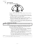
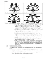
A) The Control Head has three detents; Ahead, Astern and Neu-
tral.
B) With the Control Head lever positioned in the Neutral (verti-
cal) detent, the Processor will command Neutral and the throt-
tle at Idle revolutions per minute (RPM).
C) Movement of the Control Head’s lever 15 degrees to the
Ahead or Astern detent will command Ahead or Astern clutch
engagement, while the engine RPM remains at Idle.
D) Further movement of the Control Head lever through the next
65 degrees, will increase the engine RPM in proportion to the
Control Head’s lever position.
2-4
T
ROLLING
V
ALVE
O
PERATIONL
On Control System’s equipped to control trolling valves, the oper-
ation is quite different. Troll Mode is a feature that must be
turned On and Off at the Control Head.
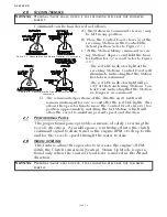
A) The Control Head has three detents; Ahead, Astern and
Neutral. To turn ON Troll Mode, place the Control Head
lever in any of the above mentioned detents.
• With the Control Head lever positioned in the Neutral (vertical)
detent, the Processor will command Neutral, the trolling valve
will be at lock-up and the throttle at Idle rpm.
B) Depress and hold the transfer button for two (2) seconds.
• The solid red indicator light on the Control Head will begin blink-
ing rapidly, indicating the system is now in Troll Mode.
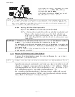
Figure 2-2: Control Head Detents
WARNING: P
ERSONAL
I
NJURY
COULD
OCCUR
IF
THE
FOLLOWING
STEPS
ARE
NOT
FOLLOWED
EXACTLY
.
NOTE: I
F
SYSTEM
IS
SET
FOR
T
WIN
S
CREW
OPERATION
,
ENSURE
ALL
C
ONTROL
H
EAD
LEVERS
ARE
IN
THE
SAME
DETENT
(N
EUTRAL
, A
HEAD
OR
A
STERN
).
Summary of Contents for ClearCommand 9000 Series
Page 132: ......
Page 133: ...APPENDIX A...
Page 134: ......
Page 139: ......
Page 140: ...Page A 4...
Page 143: ......
Page 144: ...10...
Page 148: ...Page A 18...
Page 149: ...Page A 19 TEMPLATE...
Page 150: ...Page A 20...
Page 152: ...Page A 22...
Page 154: ...Page A 24...
Page 156: ...Page A 26...
Page 157: ...Page A 27 Drawing 11488D 1 Twin Screw Single APS Connection Alternate Remote Switch...
Page 158: ...Page A 28...
Page 159: ...Page A 29 Drawing 11488D 2 Twin Screw Dual APS Connections...
Page 160: ...Page A 30...
Page 161: ...Page A 31 Drawing 11488D 3 APS Notes Page...
Page 162: ...Page A 32...
Page 164: ...Page A 34...
Page 166: ...Page A 36...
Page 170: ...Page A 40...
Page 172: ...Page A 42...
Page 176: ...Page A 46...
Page 178: ...Page C 48 ZF Mathers LLC 12125 Harbour Reach Drive Suite B Mukilteo WA 98275...
Page 179: ...APPENDIX B...
Page 180: ......
Page 234: ...Appendix B 6...
Page 238: ...Appendix B 10...
Page 242: ...Appendix B 14...
Page 247: ...Service Field Test Unit Reference Manual MM13927 Rev E 4 07...
Page 248: ......
Page 250: ...Page ii Table of Contents...
Page 264: ...SERVICE FIELD TEST UNIT MM13927 RvD 10 03 Page 3 2...
Page 265: ...APPENDIX C...
Page 266: ......
Page 267: ...Appendix C 1 Drawing 12284A 1 ClearCommand Diagram all options...
Page 268: ...Appendix C 2...
Page 269: ...Appendix C 3 Drawing 12284A 2 ClearCommand Circuit Board Connections...
Page 270: ...Appendix C 4...
Page 271: ...Appendix C 5 Drawing 12284A 3 ClearCommand Drawing Notes Page...
Page 272: ...Appendix C 6...


