


OPERATION
Page 2-4
2-6
S
TATION
T
RANSFER
Command can be transferred as follows:
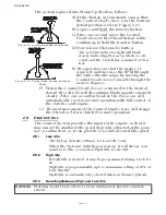
D) The commanded positions of the Throttle and Clutch will
remain unchanged for one second after the red LED lights. This
allows the operator time to move the Control Head’s lever(s) to a
position approximately matching the last Station, which will
allow the vessel to maintain present speed and direction.
2-7
P
ROPORTIONAL
P
AUSE
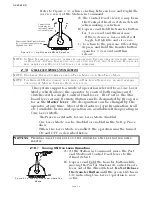
The proportional pause provides a means of safely reversing the
vessel’s direction. A variable pause is introduced into the clutch
command signal to allow time for the engine RPM’s to drop to Idle
and for the vessel’s speed through the water to slow.
2-8
W
ARM
-
UP
M
ODE
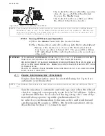
This feature allows the operator to increase the engine’s RPM,
while the Clutch remains in Neutral. Warm-Up Mode is opera-
tional only when the Control Head lever is moved in the Ahead
direction.
WARNING: P
ERSONAL
I
NJURY
COULD
OCCUR
IF
THE
FOLLOWING
STEPS
ARE
NOT
FOLLOWED
EXACTLY
.
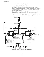
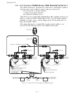
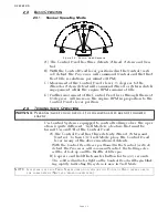
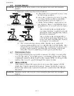
Figure 2-7: Remote Stations Before Transfer of Command
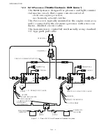
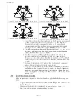
Figure 2-8: Remote Station Transfer after Transfer of
Command
A) The Station-in-Command’s lever(s) may
be left in any position.
B) Place the Control Head’s lever(s) of the
receiving Station in the Neutral/Idle
detent position (refer to Figure 2-7:).
C) At the Station taking command (receiv-
ing Station), depress and hold the trans-
fer button for 1/2 second (refer to Figure
2-8:).
• The red LED indicator light at the
receiving Station’s Control Head will
illuminate, indicating that the Station
has taken command.
• The red LED indicator light will go
OFF at the transferring Station’s Con-
trol Head, indicating that the Station
no longer is in command.
WARNING: P
ERSONAL
I
NJURY
COULD
OCCUR
IF
THE
FOLLOWING
STEPS
ARE
NOT
FOLLOWED
EXACTLY
.
Summary of Contents for ClearCommand 9000 Series
Page 132: ......
Page 133: ...APPENDIX A...
Page 134: ......
Page 139: ......
Page 140: ...Page A 4...
Page 143: ......
Page 144: ...10...
Page 148: ...Page A 18...
Page 149: ...Page A 19 TEMPLATE...
Page 150: ...Page A 20...
Page 152: ...Page A 22...
Page 154: ...Page A 24...
Page 156: ...Page A 26...
Page 157: ...Page A 27 Drawing 11488D 1 Twin Screw Single APS Connection Alternate Remote Switch...
Page 158: ...Page A 28...
Page 159: ...Page A 29 Drawing 11488D 2 Twin Screw Dual APS Connections...
Page 160: ...Page A 30...
Page 161: ...Page A 31 Drawing 11488D 3 APS Notes Page...
Page 162: ...Page A 32...
Page 164: ...Page A 34...
Page 166: ...Page A 36...
Page 170: ...Page A 40...
Page 172: ...Page A 42...
Page 176: ...Page A 46...
Page 178: ...Page C 48 ZF Mathers LLC 12125 Harbour Reach Drive Suite B Mukilteo WA 98275...
Page 179: ...APPENDIX B...
Page 180: ......
Page 234: ...Appendix B 6...
Page 238: ...Appendix B 10...
Page 242: ...Appendix B 14...
Page 247: ...Service Field Test Unit Reference Manual MM13927 Rev E 4 07...
Page 248: ......
Page 250: ...Page ii Table of Contents...
Page 264: ...SERVICE FIELD TEST UNIT MM13927 RvD 10 03 Page 3 2...
Page 265: ...APPENDIX C...
Page 266: ......
Page 267: ...Appendix C 1 Drawing 12284A 1 ClearCommand Diagram all options...
Page 268: ...Appendix C 2...
Page 269: ...Appendix C 3 Drawing 12284A 2 ClearCommand Circuit Board Connections...
Page 270: ...Appendix C 4...
Page 271: ...Appendix C 5 Drawing 12284A 3 ClearCommand Drawing Notes Page...
Page 272: ...Appendix C 6...