


INSTALLATION
Page4-12
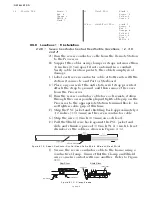
I) Connect the two-conductor cable to PB1, red lead to the
terminal labeled (+) and black lead to the terminal
labeled (-), as indicated on Figure 4-11:, page 4-14.
J) Tie wrap the power cable to the Processor’s frame.
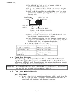
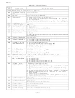
4-4.6.4 Serial Communication Cable (Location 8)
A) Install 1/2 inch (12,7mm) liquid tight cable grips into
hole (No.8) of the Port and Starboard Processors. (Refer
to Figure 4-5:, page 4-10, for entry hole location and Fig-
ure 4-4:, page 4-10, for cable grip installation.)
B) Run a four-conductor, shielded cable from the Port to
the Starboard Processors.
C) Strip back 3 inches (76,2mm) of PVC jacketing from
both ends of the cable.
D) Strip each wire 3/8 inch (9,5mm).
E) Clip the drain wire flush with the PVC jacketing on the
Starboard Processor only.
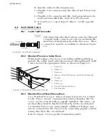
F) Place a 1 inch (25,4mm) section of shrink tubing over
each end of the cable
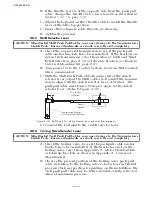
G) On the Port end of the cable, bend the drain wire back
and tuck it under the shrink tubing so that the drain
wire end is exposed past the shrink tubing. (Refer to
Figure 4-17:)
H) Shrink the Tubing with a heat gun.
I) Insert the four-conductor cable through the liquid tight
connectors and tighten the nuts
J) Secure the cables internally using a Clamp as shown in
Figure 4-13:, page 4-9. Make certain that the drain wire
makes contact with the Clamp’s metallic surface.
K) Clip the exposed drain wires flush with the Clamps.
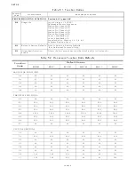
L) Connect the conductors to the terminal block as listed in
Table 4-3:
Figure 4-17: Four-Conductor Serial Communication Cable
Table 4-3: Processor Circuit Board Terminal Strip Color Coded Connections for Serial
Communication
PORT PROCESSOR
Conductor Color
STARBOARD PROCESSOR
Termination A
Termination B
TB7-6
White
TB7-6
TB7-7
Green
TB7-7
TB7-8
Red
TB7-8
Heat Shrink
1 inch
(25,4mm)
3 inches
(76,2mm)
3/8 inch
(9,53mm)
Drain Wire
Clip Drain Wire
1 inch
(25,4mm)
3 inches
(76,2mm)
3/8 inch
(9,53mm)
PORT PROCESSOR
STARBOARD PROCESSOR
Summary of Contents for ClearCommand 9000 Series
Page 132: ......
Page 133: ...APPENDIX A...
Page 134: ......
Page 139: ......
Page 140: ...Page A 4...
Page 143: ......
Page 144: ...10...
Page 148: ...Page A 18...
Page 149: ...Page A 19 TEMPLATE...
Page 150: ...Page A 20...
Page 152: ...Page A 22...
Page 154: ...Page A 24...
Page 156: ...Page A 26...
Page 157: ...Page A 27 Drawing 11488D 1 Twin Screw Single APS Connection Alternate Remote Switch...
Page 158: ...Page A 28...
Page 159: ...Page A 29 Drawing 11488D 2 Twin Screw Dual APS Connections...
Page 160: ...Page A 30...
Page 161: ...Page A 31 Drawing 11488D 3 APS Notes Page...
Page 162: ...Page A 32...
Page 164: ...Page A 34...
Page 166: ...Page A 36...
Page 170: ...Page A 40...
Page 172: ...Page A 42...
Page 176: ...Page A 46...
Page 178: ...Page C 48 ZF Mathers LLC 12125 Harbour Reach Drive Suite B Mukilteo WA 98275...
Page 179: ...APPENDIX B...
Page 180: ......
Page 234: ...Appendix B 6...
Page 238: ...Appendix B 10...
Page 242: ...Appendix B 14...
Page 247: ...Service Field Test Unit Reference Manual MM13927 Rev E 4 07...
Page 248: ......
Page 250: ...Page ii Table of Contents...
Page 264: ...SERVICE FIELD TEST UNIT MM13927 RvD 10 03 Page 3 2...
Page 265: ...APPENDIX C...
Page 266: ......
Page 267: ...Appendix C 1 Drawing 12284A 1 ClearCommand Diagram all options...
Page 268: ...Appendix C 2...
Page 269: ...Appendix C 3 Drawing 12284A 2 ClearCommand Circuit Board Connections...
Page 270: ...Appendix C 4...
Page 271: ...Appendix C 5 Drawing 12284A 3 ClearCommand Drawing Notes Page...
Page 272: ...Appendix C 6...