TROUBLESHOOTING
Page B10-1
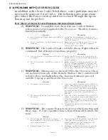
B10 PROBLEMS WITHOUT ERROR CODES
In addition to the Error Codes listed above, some problems may not
necessarily generate Error Codes. The following give some exam-
ples where the Processor may not detect a fault, though the opera-
tion may not be perfect:
B10-1B
ASIC
C
ONTROL
S
YSTEM
P
ROBLEMS
W
ITHOUT
E
RROR
C
ODES
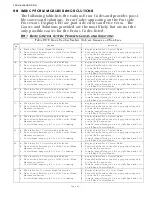
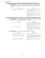
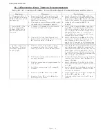
A)
SYMPTOM:
No audible tones heard at one Control Station
when power is first applied to the Processor. All other features
function normally.
B)
SYMPTOM:
The Control Head’s red LED doesn’t light when in
command, but otherwise functions properly.
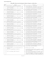
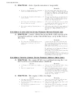
C)
SYMPTOM:
When power is turned ON to the Processor, there
are no tones from any of the Remote Stations, the Control Head
red LED does not light when the Transfer Button is pressed,
and the Display is not lit at the Processor
.
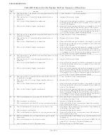
D)
SYMPTOM:
The engine begins to turn-over while starting and
then stops. A slow repetitive tone is heard from all Remote Sta-
tions.
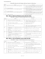
Cause
Remedy
a. Incorrectly wired Station Harness/ Cable
or Pigtail.
a. Verify that the black wire is properly con-
nected to pin 1 on the Control Head and Pin
8 at the Processor.
b. The Control Head’s Sound Transducer is
defective.
b. Measure the AC voltage at pins 1 & 3 of the
Control Head. If 20- 25 VAC is present,
replace the Control Head.
Cause
Remedy
a. Incorrectly wired Station Harness/ Cable
or Pigtail.
a. Verify that the brown wire is properly con-
nected to pin 2 on the Control head and pin 2
at the Processor.
b. The Control Head’s red LED or circuit is
open.
b. Measure the DC voltage at pins 2 & 3 at the
Control. The measurement will be approxi-
mately 2.20 VDC when the red LED is lit. If
4.00 VDC is measured, the red LED or its cir-
cuit is open. Replace the Control Head.
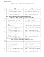
Cause
Remedy
a. No power to the Processor.
a. Disconnect the Power Harness from the Pro-
cessor. Measure the DC voltage at pins 10 (+)
and 11 (-) of the Harness plug. If 12 or 24
VDC is not present, check the circuit break-
ers, switches and cables feeding power to the
Processor. Correct the power source as
required.
b. The battery’s polarity is reversed at the
Processor.
b. Disconnect the Power Harness from the Pro-
cessor. Connect a voltmeter’s red lead to pin
10 and the black lead to pin 11 of the Har-
ness’s plug. If negative voltage is measured,
reverse the wires.
c. Defective Processor.
c. If Causes a. and b. were not the fault, replace
the Processor.
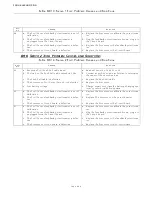
Cause
Remedy
a. The voltage available at the Processor
has dropped too low, due to the starter’s
current requirement
a. Supply power to the Processor from a battery
other that the starting battery or supply
power from two sources through an APS
(Automatic Power Selector)
b. Battery charge is too low
b. Recharge/ replace the battery or supply bat-
tery power from two sources through an
APS.
Summary of Contents for ClearCommand 9000 Series
Page 132: ......
Page 133: ...APPENDIX A...
Page 134: ......
Page 139: ......
Page 140: ...Page A 4...
Page 143: ......
Page 144: ...10...
Page 148: ...Page A 18...
Page 149: ...Page A 19 TEMPLATE...
Page 150: ...Page A 20...
Page 152: ...Page A 22...
Page 154: ...Page A 24...
Page 156: ...Page A 26...
Page 157: ...Page A 27 Drawing 11488D 1 Twin Screw Single APS Connection Alternate Remote Switch...
Page 158: ...Page A 28...
Page 159: ...Page A 29 Drawing 11488D 2 Twin Screw Dual APS Connections...
Page 160: ...Page A 30...
Page 161: ...Page A 31 Drawing 11488D 3 APS Notes Page...
Page 162: ...Page A 32...
Page 164: ...Page A 34...
Page 166: ...Page A 36...
Page 170: ...Page A 40...
Page 172: ...Page A 42...
Page 176: ...Page A 46...
Page 178: ...Page C 48 ZF Mathers LLC 12125 Harbour Reach Drive Suite B Mukilteo WA 98275...
Page 179: ...APPENDIX B...
Page 180: ......
Page 234: ...Appendix B 6...
Page 238: ...Appendix B 10...
Page 242: ...Appendix B 14...
Page 247: ...Service Field Test Unit Reference Manual MM13927 Rev E 4 07...
Page 248: ......
Page 250: ...Page ii Table of Contents...
Page 264: ...SERVICE FIELD TEST UNIT MM13927 RvD 10 03 Page 3 2...
Page 265: ...APPENDIX C...
Page 266: ......
Page 267: ...Appendix C 1 Drawing 12284A 1 ClearCommand Diagram all options...
Page 268: ...Appendix C 2...
Page 269: ...Appendix C 3 Drawing 12284A 2 ClearCommand Circuit Board Connections...
Page 270: ...Appendix C 4...
Page 271: ...Appendix C 5 Drawing 12284A 3 ClearCommand Drawing Notes Page...
Page 272: ...Appendix C 6...


