OPERATION
Page 2-7
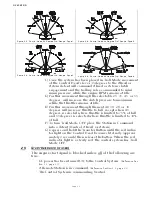
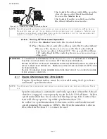
2-10.2 Turning OFF One Lever Operation
A)Place the Master lever into the Neutral detent.
B)Place the inactive Control Head lever into the Neutral detent.
• Whenever the inactive lever is moved to the Neutral detent,
One Lever operation is turned OFF. The green LED will turn
OFF, indicating that the control system is now in normal oper-
ating mode.
2-11 E
NGINE
S
YNCHRONIZATION
(T
WIN
S
CREW
)
Engine Synchronization must be selected during Set Up to have
automatic synchronization.
Synchronization is automatic and only operates when the Ahead
clutch is engaged, consequently it can be left ON full time. When
synchronization has been selected during set up, the Control Sys-
tem will always power-up with synchronization ON.
In order for synchronization to become active and work toward
synchronizing the engines' RPM's, the Synchronization Criteria
described in Section 2-11.2 must be met.
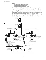
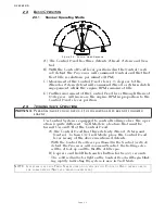
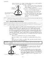
Figure 2-13: Step B) One Lever Operation Mode
•The Control Head lever which the operator
chose to move out of the Ahead detent,
becomes the
Master
lever
.
•The Control Head lever which was left in
the Ahead detent is now inactive.
NOTE: T
HE
C
ONTROL
H
EAD
LEVER
DESIGNATED
BY
THE
OPERATOR
TO
BE
INACTIVE
IN
O
NE
L
EVER
O
PERATION
,
MAY
BE
LEFT
IN
THE
A
HEAD
DETENT
OR
MOVED
FULLY
FORWARD
. M
OVING
THE
LEVER
FULLY
FORWARD
IS
RECOMMENDED
,
BECAUSE
IT
MOVES
IT
OUT
OF
THE
WAY
AND
PRE
-
VENTS
ACCIDENTAL
BUMPS
WHILE
OPERATING
.
WARNING: I
T
IS
STRONGLY
RECOMMENDED
THAT
THE
M
ASTER
LEVER
IS
RETURNED
TO
THE
N
EU
-
TRAL
/I
DLE
POSITION
PRIOR
TO
TURNING
OFF O
NE
L
EVER
O
PERATION
.
D
O
NOT
ATTEMPT
TO
TRANSFER
COMMAND
FROM
ONE
R
EMOTE
S
TATION
TO
ANOTHER
WHILE
IN
O
NE
L
EVER
O
PERATION
. A
LWAYS
TURN
O
NE
L
EVER
O
PERATION
OFF
PRIOR
TO
TRANSFERRING
.
F
AILURE
TO
OBSERVE
THESE
RECOMMENDATIONS
MAY
RESULT
IN
A
SUDDEN
CHANGE
IN
THE
VESSEL
’
S
DIRECTION
.
NOTE: T
HE
C
ONTROL
S
YSTEM
OFFERS
TWO
TYPES
OF
SYNCHRONIZATION
, A
CTIVE
OR
E
QUAL
T
HROT
-
TLE
.
Summary of Contents for ClearCommand 9000 Series
Page 132: ......
Page 133: ...APPENDIX A...
Page 134: ......
Page 139: ......
Page 140: ...Page A 4...
Page 143: ......
Page 144: ...10...
Page 148: ...Page A 18...
Page 149: ...Page A 19 TEMPLATE...
Page 150: ...Page A 20...
Page 152: ...Page A 22...
Page 154: ...Page A 24...
Page 156: ...Page A 26...
Page 157: ...Page A 27 Drawing 11488D 1 Twin Screw Single APS Connection Alternate Remote Switch...
Page 158: ...Page A 28...
Page 159: ...Page A 29 Drawing 11488D 2 Twin Screw Dual APS Connections...
Page 160: ...Page A 30...
Page 161: ...Page A 31 Drawing 11488D 3 APS Notes Page...
Page 162: ...Page A 32...
Page 164: ...Page A 34...
Page 166: ...Page A 36...
Page 170: ...Page A 40...
Page 172: ...Page A 42...
Page 176: ...Page A 46...
Page 178: ...Page C 48 ZF Mathers LLC 12125 Harbour Reach Drive Suite B Mukilteo WA 98275...
Page 179: ...APPENDIX B...
Page 180: ......
Page 234: ...Appendix B 6...
Page 238: ...Appendix B 10...
Page 242: ...Appendix B 14...
Page 247: ...Service Field Test Unit Reference Manual MM13927 Rev E 4 07...
Page 248: ......
Page 250: ...Page ii Table of Contents...
Page 264: ...SERVICE FIELD TEST UNIT MM13927 RvD 10 03 Page 3 2...
Page 265: ...APPENDIX C...
Page 266: ......
Page 267: ...Appendix C 1 Drawing 12284A 1 ClearCommand Diagram all options...
Page 268: ...Appendix C 2...
Page 269: ...Appendix C 3 Drawing 12284A 2 ClearCommand Circuit Board Connections...
Page 270: ...Appendix C 4...
Page 271: ...Appendix C 5 Drawing 12284A 3 ClearCommand Drawing Notes Page...
Page 272: ...Appendix C 6...

