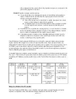
able component of the system allows the propulsion engine to overspeed or the
pitch of the propeller to increase.
184.620
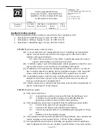
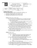
Propulsion engine control systems.
(a)
A vessel must have two independent means of controlling each propulsion
engine. Control must be provided for the engine speed, direction of shaft
rotation, and engine shutdown.
(1)
One of the means may be the ability to readily disconnect the remote
engine control linkage to permit local operation.
(2)
A multiple engine vessel with independent remote propulsion control
for each engine need not have a second means of controlling each
engine.
(a)
In addition to the requirements of paragraph (a), a vessel must have a reliable
means for shutting down a propulsion engine, at the main pilothouse control
station, which is independent of the engine's speed control.
(b)
A propulsion engine control system, including pilothouse control, must be
designed so that a loss of power to the control system does not result in an
increase in shaft speed or propeller pitch.
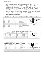
The ZF Mathers ClearCommand 9000 Series (electronic throttle, servo clutch version) marine
engine controls offer single lever control of speed and direction. Each enclosure houses an
independent Control Processor and requires separate power supplies. The system operates on 12
or 24VDC power and can have up to five remote stations depending on the application. The
system sequences the operation of speed and shift in order to prevent an inexperienced operator
from mishandling the engine or transmission.
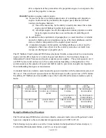
A standard feature is an alarm contact (normally open) to interface with the main alarm system of
the vessel. This switch will open and activate the alarm system with a power loss or CPU failure.
In addition, ZF Mathers provides audible tones at the Control Head locations to indicate system
faults.
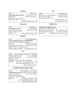
ITEM
NUMBER
FAILED
COMPONENT
ALARM
STATUS
INITIAL
RESULT
FINAL
OUTCOME
1 ZF
MATHERS
CONTROL HEAD
AUDIBLE TONE WILL
SOUND AT CONTROL
HEAD
THROTTLE RESETS
TO IDLE
NO INCREASE IN
ENGINE RPM
CLUTCH SHIFTS TO
NEUTRAL
NO INCREASE IN
SHAFT SPEED
2
LOSS OF POWER
SUPPLY
ALARM CIRCUIT
WILL OPEN
THROTTLE RESETS
TO IDLE
CLUTCH REMAINS
AT LAST
COMMANDED
POSITION
NO INCREASE IN
ENGINE RPM
NO INCREASE IN
SHAFT SPEED
Design Verification Test Procedure
The ClearCommand 9000 Series (electronic throttle, servo clutch version) Propulsion Control
System is compliant to the environmental design standards in 46 CFR 62.25-30.
Summary of Contents for ClearCommand 9000 Series
Page 132: ......
Page 133: ...APPENDIX A...
Page 134: ......
Page 139: ......
Page 140: ...Page A 4...
Page 143: ......
Page 144: ...10...
Page 148: ...Page A 18...
Page 149: ...Page A 19 TEMPLATE...
Page 150: ...Page A 20...
Page 152: ...Page A 22...
Page 154: ...Page A 24...
Page 156: ...Page A 26...
Page 157: ...Page A 27 Drawing 11488D 1 Twin Screw Single APS Connection Alternate Remote Switch...
Page 158: ...Page A 28...
Page 159: ...Page A 29 Drawing 11488D 2 Twin Screw Dual APS Connections...
Page 160: ...Page A 30...
Page 161: ...Page A 31 Drawing 11488D 3 APS Notes Page...
Page 162: ...Page A 32...
Page 164: ...Page A 34...
Page 166: ...Page A 36...
Page 170: ...Page A 40...
Page 172: ...Page A 42...
Page 176: ...Page A 46...
Page 178: ...Page C 48 ZF Mathers LLC 12125 Harbour Reach Drive Suite B Mukilteo WA 98275...
Page 179: ...APPENDIX B...
Page 180: ......
Page 234: ...Appendix B 6...
Page 238: ...Appendix B 10...
Page 242: ...Appendix B 14...
Page 247: ...Service Field Test Unit Reference Manual MM13927 Rev E 4 07...
Page 248: ......
Page 250: ...Page ii Table of Contents...
Page 264: ...SERVICE FIELD TEST UNIT MM13927 RvD 10 03 Page 3 2...
Page 265: ...APPENDIX C...
Page 266: ......
Page 267: ...Appendix C 1 Drawing 12284A 1 ClearCommand Diagram all options...
Page 268: ...Appendix C 2...
Page 269: ...Appendix C 3 Drawing 12284A 2 ClearCommand Circuit Board Connections...
Page 270: ...Appendix C 4...
Page 271: ...Appendix C 5 Drawing 12284A 3 ClearCommand Drawing Notes Page...
Page 272: ...Appendix C 6...


