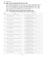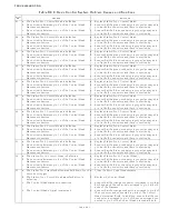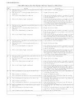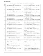
TROUBLESHOOTING
PageB5-6
2. The potentiometer is out of calibration.
3. The potentiometer is defective.
4. The Control Circuit is defective.
The Servo 1 feedback signal can be viewed within the Diagnostic
Menu. The Value displayed depends on the direction and
amount of push-pull cable travel. As a general rule:
• When the Value displayed is
1023
or
0
, the problem is with
the wiring between the potentiometer and plug.
• If the displayed Value varies, the potentiometer is defective.
• When the Value is slightly too high or too low when fully
extended, the potentiometer requires calibration.
B5-2.2 One Long, One Short - High Repetitive Rate Tones
This tone is also referred to as a
Jam Tone. When sounded, Servo
1 is unable to reach the commanded position. In most cases
when a Jam Tone is encountered, it can be cleared by moving the
Control Head lever back to the point prior to where the tone was
first encountered.
The tone will be accompanied by Error Code 62 and is typically
caused by one of the following reasons:
•
Stiff or frozen selector lever.
• Misadjusted push-pull cable.
• Defective push-pull cable.
• Low battery voltage.
• Defective Processor.
In order to isolate the cause to one of these five items, follow the
steps below:
A) Disconnect the push-pull cable from the selector lever.
B) Move the Control Head lever to Ahead, Astern, and back to
Neutral.
• If the tone ceases continue with step C).
• If the tone is still present, skip ahead to step D).
C) Grab a hold of the selector lever and manually reposition
the lever.
• If the selector lever is very stiff it needs servicing.
• If the selector lever moves freely, the push-pull cable’s travel is
misadjusted and needs to be corrected.
D) If the tone did not cease in step B), remove the push-pull
cable from the Processor.
E) Move the Control Head lever back and forth from Neutral
to Ahead to Astern.
• If the tone ceases, the push-pull cable is defective and needs to
be replaced.
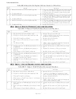
Figure B5-24: One Long, One Short - High Repetitive Rate Tones
Summary of Contents for ClearCommand 9000 Series
Page 132: ......
Page 133: ...APPENDIX A...
Page 134: ......
Page 139: ......
Page 140: ...Page A 4...
Page 143: ......
Page 144: ...10...
Page 148: ...Page A 18...
Page 149: ...Page A 19 TEMPLATE...
Page 150: ...Page A 20...
Page 152: ...Page A 22...
Page 154: ...Page A 24...
Page 156: ...Page A 26...
Page 157: ...Page A 27 Drawing 11488D 1 Twin Screw Single APS Connection Alternate Remote Switch...
Page 158: ...Page A 28...
Page 159: ...Page A 29 Drawing 11488D 2 Twin Screw Dual APS Connections...
Page 160: ...Page A 30...
Page 161: ...Page A 31 Drawing 11488D 3 APS Notes Page...
Page 162: ...Page A 32...
Page 164: ...Page A 34...
Page 166: ...Page A 36...
Page 170: ...Page A 40...
Page 172: ...Page A 42...
Page 176: ...Page A 46...
Page 178: ...Page C 48 ZF Mathers LLC 12125 Harbour Reach Drive Suite B Mukilteo WA 98275...
Page 179: ...APPENDIX B...
Page 180: ......
Page 234: ...Appendix B 6...
Page 238: ...Appendix B 10...
Page 242: ...Appendix B 14...
Page 247: ...Service Field Test Unit Reference Manual MM13927 Rev E 4 07...
Page 248: ......
Page 250: ...Page ii Table of Contents...
Page 264: ...SERVICE FIELD TEST UNIT MM13927 RvD 10 03 Page 3 2...
Page 265: ...APPENDIX C...
Page 266: ......
Page 267: ...Appendix C 1 Drawing 12284A 1 ClearCommand Diagram all options...
Page 268: ...Appendix C 2...
Page 269: ...Appendix C 3 Drawing 12284A 2 ClearCommand Circuit Board Connections...
Page 270: ...Appendix C 4...
Page 271: ...Appendix C 5 Drawing 12284A 3 ClearCommand Drawing Notes Page...
Page 272: ...Appendix C 6...


