


SEA TRIALS
Page7-12
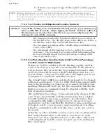
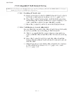
7-16.3 Record Parameters
Record information onto the following appropriate Processor
Parameter Table only after ALL information has been recorded in
Section 7-16.2 Control System Checks
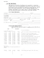
PORT
STARBOARD
YES
NO
YES
NO
Are the power cables protected by 10 Ampere Circuit Break-
ers?
YES
NO
YES
NO
If separate power supplies are used for the Port and Starboard
Processors, do they have a common ground?
At the Battery
____________
VDC
At the Processor
____________
VDC
At the Battery
____________
VDC
At the Processor
____________
VDC
What is the Voltage when not being charged?
At the Battery
____________
VDC
At the Processor
____________
VDC
At the Battery
____________
VDC
At the Processor
____________
VDC
What is the Voltage when connected to Shore Power?
At the Battery
____________
VDC
At the Processor
____________
VDC
At the Battery
____________
VDC
At the Processor
____________
VDC
What is the Voltage when the engines are running?
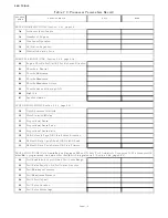
Dock Trials:
PORT
STARBOARD
YES
NO
YES
NO
Does the engine start when the Control System is turned
OFF?
YES
NO
YES
NO
Does the Engine Stop Switch function at all Stations, regard-
less of RPM?
YES
NO
YES
NO
Can all Remote Stations take command?
YES
NO
YES
NO
Does the Warm-up Indicator Light blink in Ahead?
RPM__________________ RPM__________________ What is the Low Idle RPM?
RPM__________________ RPM__________________ High Idle RPM (optional)
YES
NO
YES
NO
Does the vessel surge forward with Control Head lever in the
Ahead Detent?
Sea Trials:
PORT
STARBOARD
RPM__________________ RPM__________________ What is the Full Throttle RPM?
YES
NO
YES
NO
Do the Dual Control Head levers match position and RPM
throughout the speed range?
Seconds__________________ Seconds__________________ The Full Speed Reversal Delay is set for how many seconds?
YES
NO
YES
NO
Is Synchronization operational?
Station 1
____________
Station 2
____________
Station 1
____________
Station 2
____________
What is the length of the Control Head Harness?
Station 3
____________
Station 4
____________
Station 3
____________
Station 4
____________
Station 5
____________
Station 5
____________
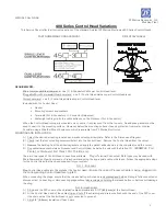
Summary of Contents for ClearCommand 9000 Series
Page 132: ......
Page 133: ...APPENDIX A...
Page 134: ......
Page 139: ......
Page 140: ...Page A 4...
Page 143: ......
Page 144: ...10...
Page 148: ...Page A 18...
Page 149: ...Page A 19 TEMPLATE...
Page 150: ...Page A 20...
Page 152: ...Page A 22...
Page 154: ...Page A 24...
Page 156: ...Page A 26...
Page 157: ...Page A 27 Drawing 11488D 1 Twin Screw Single APS Connection Alternate Remote Switch...
Page 158: ...Page A 28...
Page 159: ...Page A 29 Drawing 11488D 2 Twin Screw Dual APS Connections...
Page 160: ...Page A 30...
Page 161: ...Page A 31 Drawing 11488D 3 APS Notes Page...
Page 162: ...Page A 32...
Page 164: ...Page A 34...
Page 166: ...Page A 36...
Page 170: ...Page A 40...
Page 172: ...Page A 42...
Page 176: ...Page A 46...
Page 178: ...Page C 48 ZF Mathers LLC 12125 Harbour Reach Drive Suite B Mukilteo WA 98275...
Page 179: ...APPENDIX B...
Page 180: ......
Page 234: ...Appendix B 6...
Page 238: ...Appendix B 10...
Page 242: ...Appendix B 14...
Page 247: ...Service Field Test Unit Reference Manual MM13927 Rev E 4 07...
Page 248: ......
Page 250: ...Page ii Table of Contents...
Page 264: ...SERVICE FIELD TEST UNIT MM13927 RvD 10 03 Page 3 2...
Page 265: ...APPENDIX C...
Page 266: ......
Page 267: ...Appendix C 1 Drawing 12284A 1 ClearCommand Diagram all options...
Page 268: ...Appendix C 2...
Page 269: ...Appendix C 3 Drawing 12284A 2 ClearCommand Circuit Board Connections...
Page 270: ...Appendix C 4...
Page 271: ...Appendix C 5 Drawing 12284A 3 ClearCommand Drawing Notes Page...
Page 272: ...Appendix C 6...