


INSTALLATION
Page4-8
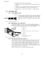
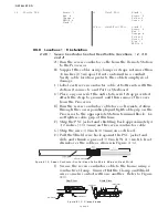
4-4.4.4 9221 (Throttle Electronic and Clutch Solenoid) Cable Hole
Locations
4-4.5
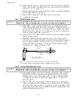
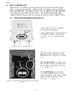
9000 Series Circuit Board Termination Points
On the 9000 Series Processors, in lieu of using Harnesses for
engine, clutch, or troll connections the Processors can be ordered
with no pigtails installed or the pigtails be removed. The above
connections must then be hard-wired directly to the circuit
board.
Refer to Table 4-1: for the Processor being used in this applica-
tion.
Locations 1 - 9 circuit board termination points are the same for
all Processors and are shown on Figure 4-6:, page 4-11.
Refer to Figure 4-6:, page 4-6, for specific termination points for
the engine, clutch or troll connections required for the Processor
being used in this application.
1. Station 5
2. Station 3
3. Station 1
4. Alarm, Clutch Pressure, and Start Inter-
lock
5. Power
6. Station 4
7. Station 2
8. Serial Communication
9. Tachometer
10. Clutch Solenoids
11. Not Used
12. Throttle Signal
Figure 4-10: 9221 Enclosure Cable Holes
12279
Figure 4-11: 9000 Series Circuit Board Hard-Wired Termination Points
Summary of Contents for ClearCommand 9000 Series
Page 132: ......
Page 133: ...APPENDIX A...
Page 134: ......
Page 139: ......
Page 140: ...Page A 4...
Page 143: ......
Page 144: ...10...
Page 148: ...Page A 18...
Page 149: ...Page A 19 TEMPLATE...
Page 150: ...Page A 20...
Page 152: ...Page A 22...
Page 154: ...Page A 24...
Page 156: ...Page A 26...
Page 157: ...Page A 27 Drawing 11488D 1 Twin Screw Single APS Connection Alternate Remote Switch...
Page 158: ...Page A 28...
Page 159: ...Page A 29 Drawing 11488D 2 Twin Screw Dual APS Connections...
Page 160: ...Page A 30...
Page 161: ...Page A 31 Drawing 11488D 3 APS Notes Page...
Page 162: ...Page A 32...
Page 164: ...Page A 34...
Page 166: ...Page A 36...
Page 170: ...Page A 40...
Page 172: ...Page A 42...
Page 176: ...Page A 46...
Page 178: ...Page C 48 ZF Mathers LLC 12125 Harbour Reach Drive Suite B Mukilteo WA 98275...
Page 179: ...APPENDIX B...
Page 180: ......
Page 234: ...Appendix B 6...
Page 238: ...Appendix B 10...
Page 242: ...Appendix B 14...
Page 247: ...Service Field Test Unit Reference Manual MM13927 Rev E 4 07...
Page 248: ......
Page 250: ...Page ii Table of Contents...
Page 264: ...SERVICE FIELD TEST UNIT MM13927 RvD 10 03 Page 3 2...
Page 265: ...APPENDIX C...
Page 266: ......
Page 267: ...Appendix C 1 Drawing 12284A 1 ClearCommand Diagram all options...
Page 268: ...Appendix C 2...
Page 269: ...Appendix C 3 Drawing 12284A 2 ClearCommand Circuit Board Connections...
Page 270: ...Appendix C 4...
Page 271: ...Appendix C 5 Drawing 12284A 3 ClearCommand Drawing Notes Page...
Page 272: ...Appendix C 6...