


INSTALLATION
Page4-18
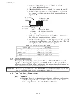
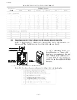
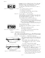
D) Strip back the PVC jacket to within 1/2 inch
(12,7mm) of the enclosure.
E) Clip the shield wire to 3/4 inch (19,1mm) of length.
F) Pull back the shield wire and solder to a 2 1/2 inch
(63,5mm), 18 AWG, green/yellow wire as shown in
Figure 4-26:.
G) Slide a 1 inch (25,4mm) section of heat-shrink over
the soldered connection and shrink.
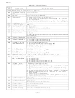
H) The termination point on TB8 depends on the type of
engine to which the Processor is interfacing. The fol-
lowing table lists the termination points.
4-5 E
NGINE
S
TOP
S
WITCHES
An engine stop switch(s) must be located at all Remote Stations and
capable of stopping the engine at any RPM. Refer to the installation
instruction supplied with the switch and the engine installation instruc-
tions for manufactures recommendations.
4-6 P
USH
-P
ULL
C
ABLE
C
ONNECTIONS
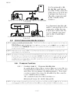
4-6.1 Processor
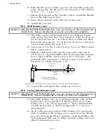
A) Remove the #10-32 jam nut and the two rubber seals from the
end of each push-pull cable that is to connect to the Proces-
sor(s) only; discard the seals, but save the nuts.
Figure 4-26: Engine Shield
Table 4-8: Throttle Termination Table
Throttle Type
Termination
DC Voltage (0 to 5.0 VDC)
Signal- TB8-5, Return- TB8-7
Current (4.0 to 20.0 mA.)
Signal- TB8-4, Return- TB8-7
PWM (0 to 99%)
Signal- TB8-3, Return- TB8-7
Frequency (
Signal- TB8-6, Return- TB8-8
Idle Validation
(+)- TB8-1, (-)- TB8-2
WARNING: A
N
E
NGINE
S
TOP
S
WITCH
AT
EACH
R
EMOTE
S
TATION
IS
AN
ABSOLUTE
REQUIREMENT
.
R
EFER
TO
CFR 46, SEC. 62.35-5
AND
ABYC P-24.5.8.
2.5 inch (63,5mm) of
18 AWG, Green/Yellow Wire
.38
inch
(9,65mm)
Solder Wire
to Shield
Cable
Heat Shrink
.75 inch (19,1mm)
of Cable Shield
12286
Summary of Contents for ClearCommand 9000 Series
Page 132: ......
Page 133: ...APPENDIX A...
Page 134: ......
Page 139: ......
Page 140: ...Page A 4...
Page 143: ......
Page 144: ...10...
Page 148: ...Page A 18...
Page 149: ...Page A 19 TEMPLATE...
Page 150: ...Page A 20...
Page 152: ...Page A 22...
Page 154: ...Page A 24...
Page 156: ...Page A 26...
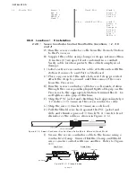
Page 157: ...Page A 27 Drawing 11488D 1 Twin Screw Single APS Connection Alternate Remote Switch...
Page 158: ...Page A 28...
Page 159: ...Page A 29 Drawing 11488D 2 Twin Screw Dual APS Connections...
Page 160: ...Page A 30...
Page 161: ...Page A 31 Drawing 11488D 3 APS Notes Page...
Page 162: ...Page A 32...
Page 164: ...Page A 34...
Page 166: ...Page A 36...
Page 170: ...Page A 40...
Page 172: ...Page A 42...
Page 176: ...Page A 46...
Page 178: ...Page C 48 ZF Mathers LLC 12125 Harbour Reach Drive Suite B Mukilteo WA 98275...
Page 179: ...APPENDIX B...
Page 180: ......
Page 234: ...Appendix B 6...
Page 238: ...Appendix B 10...
Page 242: ...Appendix B 14...
Page 247: ...Service Field Test Unit Reference Manual MM13927 Rev E 4 07...
Page 248: ......
Page 250: ...Page ii Table of Contents...
Page 264: ...SERVICE FIELD TEST UNIT MM13927 RvD 10 03 Page 3 2...
Page 265: ...APPENDIX C...
Page 266: ......
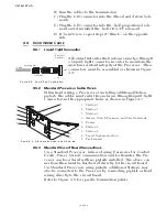
Page 267: ...Appendix C 1 Drawing 12284A 1 ClearCommand Diagram all options...
Page 268: ...Appendix C 2...
Page 269: ...Appendix C 3 Drawing 12284A 2 ClearCommand Circuit Board Connections...
Page 270: ...Appendix C 4...
Page 271: ...Appendix C 5 Drawing 12284A 3 ClearCommand Drawing Notes Page...
Page 272: ...Appendix C 6...