TROUBLESHOOTING
PageB5-5
If the Processor for this System includes the use of Back-up
Mode, this tone would indicate that there has been a
switch closure requesting Back-up Mode.
If the Processor for this System includes Integrated Sole-
noid Trolling Valve control, this tone would indicate
that there has been a Troll Solenoid error. Refer to
the Error Code displayed.
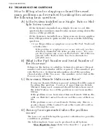
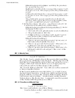
B5-1.5 Three Second Steady Tone, followed by a Slow Repetitive Tone
This tone indicates that there has been a shorted Transfer Button
on power-up. Command can be gained at any other Remote Sta-
tion, which silences the Slow Repetitive Tone.
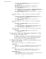
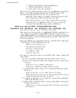
B5-1.6 Five Seconds On, Five Seconds Off - High Repetitive Rate
Tone
Loss of communication with Station Expander (SE) or the Troll
Actuator (p/n 9001). This tone cannot be cleared unless all Error
Codes (Active and In-Active) have been cleared.
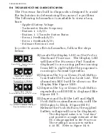
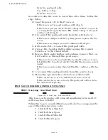
B5-1.7 Five Second Steady Tone
Loss of Serial Communication.
B5-2 S
ERVO
1 C
ONTROL
S
YSTEM
T
ONES
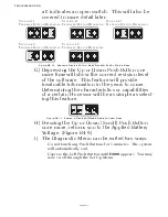
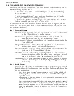
B5-2.1 One Long - One Short Tone
This tone indicates that the feedback signal, which represents
the position of the Servo 1 cross-bar, is out of the expected range.
This tone will be accompanied by Error Code
63
or
64
.
• If Error Code 63
is displayed, the signal received from the
feedback potentiometer is higher than expected. This is due
to one of the three following reasons:
1. The orange wire (ground) between the potentiometer
and plug are not making contact, or have a high resis-
tance contact.
2. The potentiometer is out of calibration.
3. The potentiometer is defective.
• If Error Code
64
is displayed, the signal received from the
feedback potentiometer is lower than expected. This is due to
one of the following reasons:
1. The green (signal) or orange (reference voltage) wires
between the potentiometer and plug are not making
contact or have a high resistance contact.
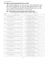
Figure B5-20: Three Second Tone, followed by a Slow Repetitive Tone
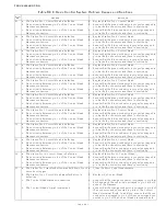
Figure B5-21: Five Seconds On, Five Seconds Off - High Repetitive Rate Tone
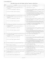
Figure B5-22: Five Second Steady Tone
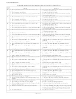
Figure B5-23: One Long - One Short Tone
Summary of Contents for ClearCommand 9000 Series
Page 132: ......
Page 133: ...APPENDIX A...
Page 134: ......
Page 139: ......
Page 140: ...Page A 4...
Page 143: ......
Page 144: ...10...
Page 148: ...Page A 18...
Page 149: ...Page A 19 TEMPLATE...
Page 150: ...Page A 20...
Page 152: ...Page A 22...
Page 154: ...Page A 24...
Page 156: ...Page A 26...
Page 157: ...Page A 27 Drawing 11488D 1 Twin Screw Single APS Connection Alternate Remote Switch...
Page 158: ...Page A 28...
Page 159: ...Page A 29 Drawing 11488D 2 Twin Screw Dual APS Connections...
Page 160: ...Page A 30...
Page 161: ...Page A 31 Drawing 11488D 3 APS Notes Page...
Page 162: ...Page A 32...
Page 164: ...Page A 34...
Page 166: ...Page A 36...
Page 170: ...Page A 40...
Page 172: ...Page A 42...
Page 176: ...Page A 46...
Page 178: ...Page C 48 ZF Mathers LLC 12125 Harbour Reach Drive Suite B Mukilteo WA 98275...
Page 179: ...APPENDIX B...
Page 180: ......
Page 234: ...Appendix B 6...
Page 238: ...Appendix B 10...
Page 242: ...Appendix B 14...
Page 247: ...Service Field Test Unit Reference Manual MM13927 Rev E 4 07...
Page 248: ......
Page 250: ...Page ii Table of Contents...
Page 264: ...SERVICE FIELD TEST UNIT MM13927 RvD 10 03 Page 3 2...
Page 265: ...APPENDIX C...
Page 266: ......
Page 267: ...Appendix C 1 Drawing 12284A 1 ClearCommand Diagram all options...
Page 268: ...Appendix C 2...
Page 269: ...Appendix C 3 Drawing 12284A 2 ClearCommand Circuit Board Connections...
Page 270: ...Appendix C 4...
Page 271: ...Appendix C 5 Drawing 12284A 3 ClearCommand Drawing Notes Page...
Page 272: ...Appendix C 6...


