


TROUBLESHOOTING
PageB5-4
•
If the A/D value is 995 or higher, most likely the potentiome-
ter’s ground has been lost.
• Right hand Control Heads have a jumper between pins 3 and 5
if a Harness is used. This jumper provides the potentiometers
ground.
• Left hand Control heads have a jumper between pins 3 and 7
is a Harness is used. This jumper provides the potentiometers
ground.
• The potentiometer ground connection for Control Heads
which are hard-wired to the Processor is through the yellow
wire (pin 5 on right hand and pin 7 on left hand).
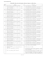
F) If the A/D value is 100 or less, one of Error Codes 23
-
32
(Control Head # Faulted Low) will be shown.
•
If the A/D value is less than 100, but greater than 75, the fol-
lowing may be the cause:
1. The Control Head’s potentiometer is out of calibration.
2. The potentiometer is defective.
3. A high resistance connection exists on pin 6 (green
wire) between the Control Head and Processor.
• If the A/D value is less than 75:
1. There is an open wire between pin 6 (green wire) of
the Control Head and the Processor.
2. There is an open wire between pin 7 (blue wire) of a
right hand Control Head and the Processor.
3. There is an open wire between pin 5 (blue wire) of a
left hand Control Head and pin 7 (blue wire) of the
Processor.
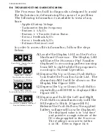
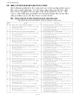
B5-1.3 Steady Tone
The Steady Tone is an indication to the operator that something
has gone wrong within the Control System. The Steady Tone will
typically be accompanied by an Error Message on the Processor’s
Display. If the tone is heard, the Processor’s Display must be
referred to in order to further diagnosis the problem.
The Transfer Button is shorted - Tone will cease when command
is taken at another Station.
If the Transfer Button becomes shorted for 12 seconds or more
during Normal Operation, a steady tone will be produced at all
Remote Stations as long as the Transfer Button remains shorted.
Full System control remains. Transferring to another Remote
Station silences the Steady Tone. Command cannot be regained
at the Station until the problem is rectified.
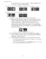
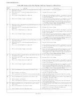
B5-1.4 Three Second Steady Tone
This tone could indicate one of three things.
Transfer Button on the Control Head in command is stuck.
Figure B5-18: Steady Tone
Figure B5-19: Three Second Tone
Summary of Contents for ClearCommand 9000 Series
Page 132: ......
Page 133: ...APPENDIX A...
Page 134: ......
Page 139: ......
Page 140: ...Page A 4...
Page 143: ......
Page 144: ...10...
Page 148: ...Page A 18...
Page 149: ...Page A 19 TEMPLATE...
Page 150: ...Page A 20...
Page 152: ...Page A 22...
Page 154: ...Page A 24...
Page 156: ...Page A 26...
Page 157: ...Page A 27 Drawing 11488D 1 Twin Screw Single APS Connection Alternate Remote Switch...
Page 158: ...Page A 28...
Page 159: ...Page A 29 Drawing 11488D 2 Twin Screw Dual APS Connections...
Page 160: ...Page A 30...
Page 161: ...Page A 31 Drawing 11488D 3 APS Notes Page...
Page 162: ...Page A 32...
Page 164: ...Page A 34...
Page 166: ...Page A 36...
Page 170: ...Page A 40...
Page 172: ...Page A 42...
Page 176: ...Page A 46...
Page 178: ...Page C 48 ZF Mathers LLC 12125 Harbour Reach Drive Suite B Mukilteo WA 98275...
Page 179: ...APPENDIX B...
Page 180: ......
Page 234: ...Appendix B 6...
Page 238: ...Appendix B 10...
Page 242: ...Appendix B 14...
Page 247: ...Service Field Test Unit Reference Manual MM13927 Rev E 4 07...
Page 248: ......
Page 250: ...Page ii Table of Contents...
Page 264: ...SERVICE FIELD TEST UNIT MM13927 RvD 10 03 Page 3 2...
Page 265: ...APPENDIX C...
Page 266: ......
Page 267: ...Appendix C 1 Drawing 12284A 1 ClearCommand Diagram all options...
Page 268: ...Appendix C 2...
Page 269: ...Appendix C 3 Drawing 12284A 2 ClearCommand Circuit Board Connections...
Page 270: ...Appendix C 4...
Page 271: ...Appendix C 5 Drawing 12284A 3 ClearCommand Drawing Notes Page...
Page 272: ...Appendix C 6...