


OPERATION
Page 2-3
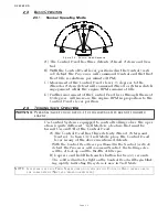
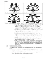
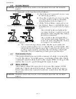
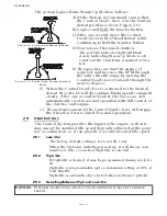
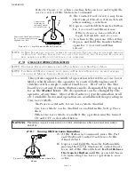
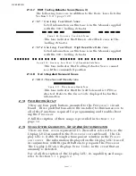
C) Once the system has been placed in Troll Mode, movement
of the Control Head’s lever 15 degrees to the Ahead or
Astern detent will command Ahead or Astern clutch
engagement and the trolling valve commanded to mini-
mum pressure, while the engine RPM remains at Idle.
D) Further movement through the selectable 25, 35, 45, or 55
degrees, will increase the clutch pressure to maximum
while the throttle remains at Idle.
E) Further movement through the next 40, 30, 20, or 10
degrees will increase throttle to full, except when 45
degrees is selected where throttle is limited to 75% of full
and 55 degrees is selected where throttle is limited to 10%
of full.
F) To turn Troll Mode OFF, place the Station-in-Command
into a detent (Neutral, Ahead, or Astern).
G) Depress and hold the Transfer Button until the red indica-
tor light on the Control Head becomes lit steady (approxi-
mately 2 seconds) then release the button. When the red
indicator light is a steady red, the control system has Troll
Mode OFF.
2-5
S
TART
I
NTERLOCK
(
IF
USED
)
The engine start signal is blocked unless all of the following are
true:
• DC power has been turned ON to the Control System.
(Reference Sec-
tion 2-1, page 2-1)
• A Remote Station is in command.
(Reference Section 2-2, page 2-1)
• The Control System is commanding Neutral.
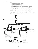
Figure 2-3: Control Head 20 Degree Troll Range - Type 1
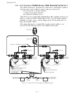
Figure 2-4: Control Head 35 Degree Troll Range - Type 2
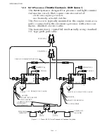
Figure 2-5: Control Head 45 Degree Troll Range - Type 3
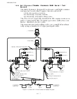
Figure 2-6: Control Head 55 Degree Troll Range - Type 4
Summary of Contents for ClearCommand 9000 Series
Page 132: ......
Page 133: ...APPENDIX A...
Page 134: ......
Page 139: ......
Page 140: ...Page A 4...
Page 143: ......
Page 144: ...10...
Page 148: ...Page A 18...
Page 149: ...Page A 19 TEMPLATE...
Page 150: ...Page A 20...
Page 152: ...Page A 22...
Page 154: ...Page A 24...
Page 156: ...Page A 26...
Page 157: ...Page A 27 Drawing 11488D 1 Twin Screw Single APS Connection Alternate Remote Switch...
Page 158: ...Page A 28...
Page 159: ...Page A 29 Drawing 11488D 2 Twin Screw Dual APS Connections...
Page 160: ...Page A 30...
Page 161: ...Page A 31 Drawing 11488D 3 APS Notes Page...
Page 162: ...Page A 32...
Page 164: ...Page A 34...
Page 166: ...Page A 36...
Page 170: ...Page A 40...
Page 172: ...Page A 42...
Page 176: ...Page A 46...
Page 178: ...Page C 48 ZF Mathers LLC 12125 Harbour Reach Drive Suite B Mukilteo WA 98275...
Page 179: ...APPENDIX B...
Page 180: ......
Page 234: ...Appendix B 6...
Page 238: ...Appendix B 10...
Page 242: ...Appendix B 14...
Page 247: ...Service Field Test Unit Reference Manual MM13927 Rev E 4 07...
Page 248: ......
Page 250: ...Page ii Table of Contents...
Page 264: ...SERVICE FIELD TEST UNIT MM13927 RvD 10 03 Page 3 2...
Page 265: ...APPENDIX C...
Page 266: ......
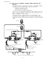
Page 267: ...Appendix C 1 Drawing 12284A 1 ClearCommand Diagram all options...
Page 268: ...Appendix C 2...
Page 269: ...Appendix C 3 Drawing 12284A 2 ClearCommand Circuit Board Connections...
Page 270: ...Appendix C 4...
Page 271: ...Appendix C 5 Drawing 12284A 3 ClearCommand Drawing Notes Page...
Page 272: ...Appendix C 6...