SET UP
Page5-28
The available Values are
20.0
to
100.0
percent of the
the maximum current available. The Default Value is
25.0
%. The Value selected must be at least 20%
above or below (Normal/Inverse) the Troll Minimum
Pressure
L2
selected.
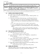
5-6.5.4.4 Function Code L6 – Troll Pulse Percentage
This Function Code selects the percentage of maxi-
mum available current applied to the proportional
solenoid when first engaging the Clutch while in
Troll.
The available Values for this Function are
00.0
% to
100.0
% and the default Value is
25.0
%.
The Value is automatically changed to the same
Value selected with Function Code
L3
Troll Maxi-
mum Pressure.
5-6.5.5 Troubleshooting Functions
5-6.5.1 Basic Processor Troubleshooting Functions
5-6.5.1.1
Function Code H0 - Diagnostics
This Function is used during troubleshooting and is
explained in detail in Section B-1.5, page B-7.
5-6.5.1.2 Function Code H1 – Return to Factory Defaults
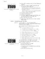
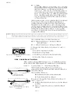
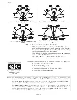
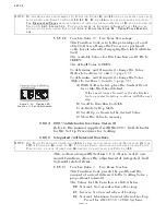
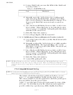
Figure 5-56: Display LED
Function L3 Set Up Activated
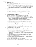
To determine, and if required, change the Value
(Refer to Sections 5-2 and 5-3, page 5-5):
A)Move the Control Head lever to the Ahead
detent.
B) Scroll to Function Code
L3
.
C) Activate Set Up Mode.
D) Scroll Up or Down to the appropriate Value for
the Trolling Valve.
E) Store the Value to memory
NOTE: D
O
NOT
MAKE
ANY
ADJUSTMENTS
TO
F
UNCTION
C
ODES
L5
AND
L6
UNTIL
THE
VESSEL
HAS
BEEN
SEA
-
TRIALED
AND
F
UNCTION
C
ODES
L0, L1, L2, L3,
AND
L4
HAVE
BEEN
PROPERLY
ADJUSTED
.
F
OR
I
NTEGRATED
T
ROLL
DETAILED
INSTRUCTIONS
ON
THE
ADJUSTMENT
OF
L5
CAN
BE
FOUND
IN
S
ECTION
5-6.4.1.6
PAGE
5-33. T
HE
ADJUSTMENT
OF
I
NTEGRATED
S
OLENOID
T
ROLL
L6
CAN
BE
FOUND
IN
THE
FOLLOWING
S
ECTION
5-6.5.4.4, F
UNCTION
C
ODE
L6 – T
ROLL
P
ULSE
P
ERCENT
-
AGE
.
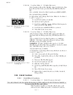
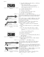
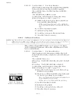
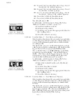
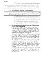
Figure 5-57: Display LED
Function L2 Set Up Activated
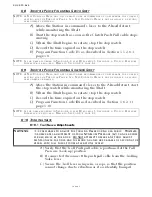
To determine, and if required, change the Value
(Refer to Sections 5-2 and 5-3, page 5-5):
A)With Troll selected, move the Control Head
lever to the Ahead detent.
• If the vessel lunges forward or the shaft takes
too long to start rotating, continue with the next
step.
B) Scroll to Function Code
L6
.
C) Activate Set Up Mode.
D) Scroll Up or Down to the desired Value.
E) Store the Value to memory
Summary of Contents for ClearCommand 9000 Series
Page 132: ......
Page 133: ...APPENDIX A...
Page 134: ......
Page 139: ......
Page 140: ...Page A 4...
Page 143: ......
Page 144: ...10...
Page 148: ...Page A 18...
Page 149: ...Page A 19 TEMPLATE...
Page 150: ...Page A 20...
Page 152: ...Page A 22...
Page 154: ...Page A 24...
Page 156: ...Page A 26...
Page 157: ...Page A 27 Drawing 11488D 1 Twin Screw Single APS Connection Alternate Remote Switch...
Page 158: ...Page A 28...
Page 159: ...Page A 29 Drawing 11488D 2 Twin Screw Dual APS Connections...
Page 160: ...Page A 30...
Page 161: ...Page A 31 Drawing 11488D 3 APS Notes Page...
Page 162: ...Page A 32...
Page 164: ...Page A 34...
Page 166: ...Page A 36...
Page 170: ...Page A 40...
Page 172: ...Page A 42...
Page 176: ...Page A 46...
Page 178: ...Page C 48 ZF Mathers LLC 12125 Harbour Reach Drive Suite B Mukilteo WA 98275...
Page 179: ...APPENDIX B...
Page 180: ......
Page 234: ...Appendix B 6...
Page 238: ...Appendix B 10...
Page 242: ...Appendix B 14...
Page 247: ...Service Field Test Unit Reference Manual MM13927 Rev E 4 07...
Page 248: ......
Page 250: ...Page ii Table of Contents...
Page 264: ...SERVICE FIELD TEST UNIT MM13927 RvD 10 03 Page 3 2...
Page 265: ...APPENDIX C...
Page 266: ......
Page 267: ...Appendix C 1 Drawing 12284A 1 ClearCommand Diagram all options...
Page 268: ...Appendix C 2...
Page 269: ...Appendix C 3 Drawing 12284A 2 ClearCommand Circuit Board Connections...
Page 270: ...Appendix C 4...
Page 271: ...Appendix C 5 Drawing 12284A 3 ClearCommand Drawing Notes Page...
Page 272: ...Appendix C 6...

