


Page A-25
ZF Mathers, LLC
12125 Harbour Reach Drive, Suite B
Mukilteo, WA 98275 U.S.A.
800-546-5455 / 425-583-1900
Fax: 425-493-1569
S-214 Rev.E 5/03
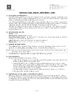
A) GENERAL INFORMATION
The APS (Automatic Power Selector), Model 13505, provides a simple, solid state solu-
tion to the need for routing redundant DC power sources for vital electronic equipment
while maintaining isolation of the DC power sources.
Two independent batteries rated at the same nominal voltage are wired to separate ter-
minals on the APS and internal diodes maintain total isolation between them. A single
output terminal is wired to the ZF Mathers Propulsion Control System.
The APS is rated for loads of up to 70 Amps on 12-24V systems. The unit is ruggedly
constructed with heavy-duty wiring studs and epoxy-potted components in an anod-
ized aluminum case.
B) APS SPECIFICATIONS
Model:
13505
Maximum Load Current:
70 amps
Operating Temperature:
-40 degrees C to +80 degrees C; derate linearly from 100% @
50 degrees C to 70% @ 80 degrees C
Voltage Drop:
0.7 VDC @ 50% load; 0.9 VDC @ full load
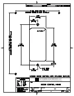
Dimensions:
3.25" x 4.5" x 3.1" (8,3 x 11,4 x 7,9 cm)
C) MATERIALS PROVIDED
The
single
APS is supplied with a hardware packet containing (6) hex nuts, (3) lock
washers, (4) self-tapping mounting screws, (1) instructions diagram.
The
twin
APS is supplied with (2) single APS hardware packets.
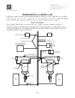
D) INSTALLATION
Refer to the installation Drawing 11488C.
1. Shut off all charging sources and disconnect the negative (ground) side of each
battery which will be wired to the APS.
2. Mount the APS(s) in a suitable location which will keep wire runs to a mini-
mum length, and is (preferably) ventilated, for cooler operation. The case of the
APS is electrically isolated from the internal diodes, so mounting on either a
metal or non-metal surface is acceptable.
3. Complete the wiring as indicated on either Drawing 11488C-1 or 11488C-2.
4. Reconnect the negative battery posts.
E) IMPORTANT NOTE ABOUT BATTERY SOURCES
Whenever the load is turned on, it can be drawing power from the batteries. There-
fore, if the batteries are not simultaneously being recharged, or if charging will not be
available for an extended period, it is recommended that the load be shut off to prevent
complete discharge of batteries.
Automatic Power Selector (APS) Model: 13505
NOTE: N
OT
ALL
OF
THE
HARDWARE
WILL
BE
USED
IN
THE
INSTALLATION
;
SOME
SPARES
ARE
PROVIDED
. N
UT
SIZE
IS
M-6.
Summary of Contents for ClearCommand 9000 Series
Page 132: ......
Page 133: ...APPENDIX A...
Page 134: ......
Page 139: ......
Page 140: ...Page A 4...
Page 143: ......
Page 144: ...10...
Page 148: ...Page A 18...
Page 149: ...Page A 19 TEMPLATE...
Page 150: ...Page A 20...
Page 152: ...Page A 22...
Page 154: ...Page A 24...
Page 156: ...Page A 26...
Page 157: ...Page A 27 Drawing 11488D 1 Twin Screw Single APS Connection Alternate Remote Switch...
Page 158: ...Page A 28...
Page 159: ...Page A 29 Drawing 11488D 2 Twin Screw Dual APS Connections...
Page 160: ...Page A 30...
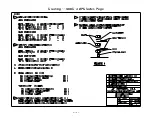
Page 161: ...Page A 31 Drawing 11488D 3 APS Notes Page...
Page 162: ...Page A 32...
Page 164: ...Page A 34...
Page 166: ...Page A 36...
Page 170: ...Page A 40...
Page 172: ...Page A 42...
Page 176: ...Page A 46...
Page 178: ...Page C 48 ZF Mathers LLC 12125 Harbour Reach Drive Suite B Mukilteo WA 98275...
Page 179: ...APPENDIX B...
Page 180: ......
Page 234: ...Appendix B 6...
Page 238: ...Appendix B 10...
Page 242: ...Appendix B 14...
Page 247: ...Service Field Test Unit Reference Manual MM13927 Rev E 4 07...
Page 248: ......
Page 250: ...Page ii Table of Contents...
Page 264: ...SERVICE FIELD TEST UNIT MM13927 RvD 10 03 Page 3 2...
Page 265: ...APPENDIX C...
Page 266: ......
Page 267: ...Appendix C 1 Drawing 12284A 1 ClearCommand Diagram all options...
Page 268: ...Appendix C 2...
Page 269: ...Appendix C 3 Drawing 12284A 2 ClearCommand Circuit Board Connections...
Page 270: ...Appendix C 4...
Page 271: ...Appendix C 5 Drawing 12284A 3 ClearCommand Drawing Notes Page...
Page 272: ...Appendix C 6...