232
CHAPTER 28
•
CLICK 400
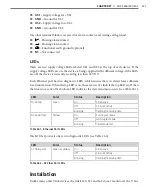
Autobaud (solid green)
The Autobaud mode is used to match baud rates with an external device. By default, the
device will attempt to match baud rates with a SmartSensor on the bus; however, the device
can be configured to autobaud with any device that supports a serial interface.
During the autobaud process, the green LED will stay on and the red LED will flash after
every autobaud cycle (the cycle time increases as latency is added after each cycle). If the
autobaud was successful, the radio will be set up as a client and the green LED will turn off
and the yellow LED will start to flash as data arrives over the bus; if the autobaud was not
successful, the green LED will turn off and the yellow LED will be solid.
Link Test in Server (flashing blue) and Client (solid blue) Modes
The Link Test modes are used to test the wireless link between two Click 400 modules. Fol-
low the steps below to perform a link test:
1
Set one of the devices in Link Test mode as a server by pressing the push-button, then
releasing when the blue LED begins flashing. A server in Link Test mode will have a
solid blue and red LED and the green LED will begin flashing as it sends data for the
test.
2
Set the other device in Link Test mode as a client by pressing the push-buttonm then
releasing when the blue LED turns on solid. The client device will have a solid red LED.
3
Watch the client to be sure it has found a server: if the device finds a server on the same
channel, the blue LED will be solid. If the blue LED does not turn on, then the client
cannot find a server.
4
Once you’re sure the client has found a server, watch the LEDs on the client to see the
results of the link test. A blinking green LED means that the client is receiving valid
link test data from the server; a flashing yellow LED means that the device is receiving
invalid link test data; and a solid yellow LED means no data is being received.
5
If the Click 400 is receiving invalid link test data, verify that the server is in link test
mode. If this does not fix the problem, then check the line of sight and the antenna for
possible problems.
6
Once the test is complete, the devices must be taken out of link test mode in order to
operate. Press and release the mode button on each device to get back to operational
mode.
Factory Reset (flashing red)
The Factory Reset operation will erase all user-configured fields and the Click 400 may have
to be reconfigured to work properly in its current application. If a device is not respond-
ing and not communicating, resetting the device may fix the problem. Once the device
is responding, restore the configuration needed for its current application (i.e. loading a
SmartSensor client driver or changing to the correct channel).
To reset the Click 400 to factory defaults, release the push-button when the red LED begins
Summary of Contents for Click 100
Page 1: ...Click 100 400 Series USER GUIDE...
Page 11: ......
Page 17: ......
Page 27: ......
Page 41: ......
Page 43: ......
Page 79: ......
Page 129: ......
Page 145: ......
Page 161: ......
Page 175: ......
Page 183: ......
Page 187: ......
Page 207: ......
Page 219: ......
Page 225: ......
Page 245: ......
Page 259: ......
Page 260: ...www wavetronix com...


