CHAPTER 17
• CLICK 211
165
Wiring the Power Plant
1
Install the Click 210 and Click 230 as outlined in Chapter 1.
2
Attach two ST 2.5 twin terminal blocks to the DIN rail next to the Click 230.
3
Attach the Click 201/202/204 (or 203, if you prefer to use that as a power supply) to the
DIN rail next to the twin terminal blocks.
4
Attach 14 AWG wires that are stripped 3/8” on both ends to the N and L screw terminal
connections on the OUT side of the Click 230 (the standard is to use white and black
wires, respectively).
5
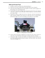
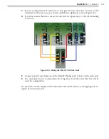
Terminate the white, or neutral, wire into one of the ports on the first twin terminal
block. Terminate the black, or line, wire into one of the ports on the second twin termi-
nal block (see Figure 17.3). For ease in wiring, use the same port on each block.
Figure 17.3 – Wiring into Twin Terminal Blocks
6
Attach 14 AWG wires that are stripped 3/8” on both ends to the second set of ports on
each of the twin terminal blocks, following the coloring of the wires coming in.
7
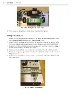
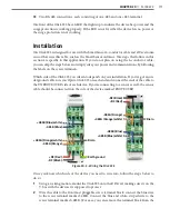
Terminate the white, or neutral, wire in the N screw terminal connection on the AC In
side of the Click 201/202/204. Terminate the black, or line, wire in the L screw terminal
connection (see Figure 17.4).
Summary of Contents for Click 100
Page 1: ...Click 100 400 Series USER GUIDE...
Page 11: ......
Page 17: ......
Page 27: ......
Page 41: ......
Page 43: ......
Page 79: ......
Page 129: ......
Page 145: ......
Page 161: ......
Page 175: ......
Page 183: ......
Page 187: ......
Page 207: ......
Page 219: ......
Page 225: ......
Page 245: ......
Page 259: ......
Page 260: ...www wavetronix com...

