134
CHAPTER 12
•
CLICK 172/174
Physical Features
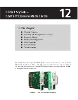
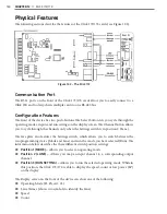
The following sections describe the features of the Click 172/174 cards (see Figure 12.2):
Figure 12.2 – The Click 172
Communication Port
The RJ-11 ports on the front of the Click 172/174 cards allow you to easily connect to a
Click 200 and to daisy-chain multiple cards to one RS-485 bus.
Configuration Features
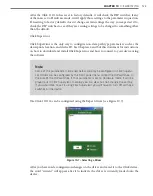
The front of the device has two push-buttons. The Select button lets you cycle through the
operating modes, inputs and run settings on the display screen. The Channel button allows
you to cycle through the channels only when the Settings switch is in position 2 (Lane).
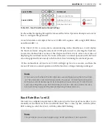
The face plate also features the Settings switch, which allows you to switch between the
two programming states (Mode and Lane) and run the mode you have selected (Run). The
information below describes the three different switch position settings:
˽
Position 1 (MODE) –
Allows you to select an operating mode.
˽
Position 2 (LANE) –
Allows you map an input channel to a corresponding output
channel.
˽
Position 3 (RUN SETTING) –
Allows you to run the selected operating mode. While in
this position, the Click 172/174 is able to display the speed, count or low power (LP)
on the display.
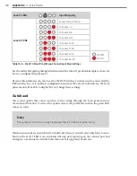
The Display screen on the front of the device can show one of the following:
˽
Operating Mode (Pr, Pu, AC, 1L)
˽
Lane Names (shows two symbols to identify the lane)
˽
Speed
˽
Count
Summary of Contents for Click 100
Page 1: ...Click 100 400 Series USER GUIDE...
Page 11: ......
Page 17: ......
Page 27: ......
Page 41: ......
Page 43: ......
Page 79: ......
Page 129: ......
Page 145: ......
Page 161: ......
Page 175: ......
Page 183: ......
Page 187: ......
Page 207: ......
Page 219: ......
Page 225: ......
Page 245: ......
Page 259: ......
Page 260: ...www wavetronix com...

