156
CHAPTER 15
•
CLICK 203
Note
Because the Click 203 is a power supply, if you are using one, you do not need a Click
201/202/204.
Physical Features
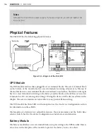
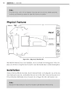
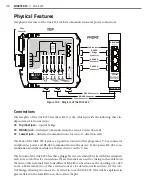
The Click 203 has the following physical features.
Figure 15.2 – Diagram of the Click 203
UPS Module
The UPS module features three pluggable screw terminal blocks. The screw terminal block
on the bottom of the module has two screw terminals for wiring AC power in. The top of
the module has two screw terminal blocks situated next to each other: the block on the right
has two screw terminals for wiring to the battery, and the block on the left has seven screw
terminals, for DC out, among other things. Wiring the device will be discussed later in the
chapter. The screw terminals are removable for easy preinstallation wiring.
The UPS module has three LEDs on the faceplate. See the On-device Configuration section
for information on these LEDs.
The faceplate also features two adjustable features, the potentiometer and the buffer time
selector switch. See the On-device Configuration section for more information.
Battery Module
The battery module has a screw terminal block on top for wiring to the UPS module. There’s
also a fuse on the faceplate of the module to protect the battery in case of a short.
Summary of Contents for Click 100
Page 1: ...Click 100 400 Series USER GUIDE...
Page 11: ......
Page 17: ......
Page 27: ......
Page 41: ......
Page 43: ......
Page 79: ......
Page 129: ......
Page 145: ......
Page 161: ......
Page 175: ......
Page 183: ......
Page 187: ......
Page 207: ......
Page 219: ......
Page 225: ......
Page 245: ......
Page 259: ......
Page 260: ...www wavetronix com...

