


114
CHAPTER 10
•
CLICK 112/114
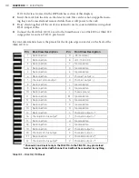
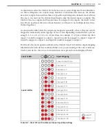
S4: Input Mapping
1
2
3
4
Channel
Off
Off
Off
Off
Software mode
Off
Off
Off
On
1–2
Off
Off
On
Off
3–4
Off
Off
On
On
5–6
Off
On
Off
Off
7–8
Off
On
Off
On
9–10
Off
On
On
Off
11–12
Off
On
On
On
13–14
On
Off
Off
Off
15–16
On
Off
Off
On
17–18
On
Off
On
Off
19–20
On
Off
On
On
21–22
On
On
Off
Off
23–24
On
On
Off
On
25–26
On
On
On
Off
27–28
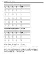
Table 10.3 – Click 112 DIP Switch Channel Input Map Settings
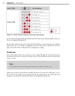
S4: Input Mapping
1
2
3
4
Channel
Off
Off
Off
Off
Software mode
Off
Off
Off
On
1–4
Off
Off
On
Off
5–8
Off
Off
On
On
9–12
Off
On
Off
Off
13–16
Off
On
Off
On
17–20
Off
On
On
Off
21–24
Off
On
On
On
25–28
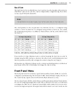
Table 10.4 – Click 114 DIP Switch Channel Input Map Settings
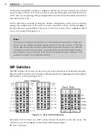
If any switch is on (up), Hardware mode is selected, meaning the inputs can only be mapped
using the DIP switches (as shown in the tables above), and Click Supervisor and the front
panel menu will be able to display the current setting, but not change it. If all switches are
off (down), Software mode is selected and Click Supervisor and the front panel menu will
be able to both display and change the current setting.
Summary of Contents for Click 100
Page 1: ...Click 100 400 Series USER GUIDE...
Page 11: ......
Page 17: ......
Page 27: ......
Page 41: ......
Page 43: ......
Page 79: ......
Page 129: ......
Page 145: ......
Page 161: ......
Page 175: ......
Page 183: ......
Page 187: ......
Page 207: ......
Page 219: ......
Page 225: ......
Page 245: ......
Page 259: ......
Page 260: ...www wavetronix com...