170
CHAPTER 19
•
CLICK 222
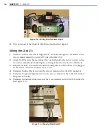
Physical Features
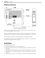
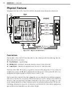
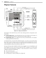
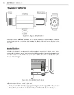
The physical features of the Click 222 include communication and power connections.
LED Indicators
T-Bus
Connector
RS-485
Bridge
Connector
RS-485 B
Connector
RS-485 A
Connector
RS-485 Connector
RS-485 Connector
Power Connector
PWR
DC Surge
OK
TD
RD
Click! 222
System Surge
Protection
www.wavetronix.com
RS-485 A
RS-485 B
RS-485 Bridge
Con
tr
ol
Da
ta
Da
ta
Figure 19.2 – Diagram of the Click 222
Connections
The faceplate of the Click 222 has three RJ-11 jacks, which provide the following three in-
dependent serial connections:
˽
Topmost jack –
control bridge
˽
Middle jack –
dedicated communications for sensor 2 detection calls
˽
Lowest jack –
dedicated communications for sensor 1 detection calls
The back of the Click 222 features a 5-position connector that plugs into a T-bus connector
and provides power and RS-485 communication to the device. It also passes RS-485 com-
munication from the module to all other devices on the T-bus.
The bottom of the Click 222 has three pluggable screw terminal blocks with four terminals
each, for a total of twelve connections. These terminals are used for wiring in the cable from
the sensor. The terminals have four different RS-485 connections, each consisting of a +485
and a -485 terminal; two of these connections are for detection calls and two for the con-
trol bridge, allowing two sensors to be wired in to each Click 222. This will be explained in
greater detail in the Installation section of this chapter.
Summary of Contents for Click 100
Page 1: ...Click 100 400 Series USER GUIDE...
Page 11: ......
Page 17: ......
Page 27: ......
Page 41: ......
Page 43: ......
Page 79: ......
Page 129: ......
Page 145: ......
Page 161: ......
Page 175: ......
Page 183: ......
Page 187: ......
Page 207: ......
Page 219: ......
Page 225: ......
Page 245: ......
Page 259: ......
Page 260: ...www wavetronix com...

