CHAPTER 27
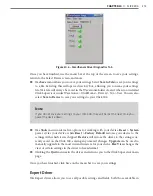
• CLICK 340/341/342
227
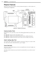
˽
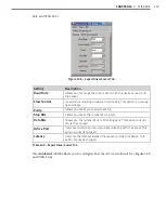
US1 –
Supply voltage for +US1
˽
GND –
Ground for US1
˽
US2 –
Supply voltage for +US2
˽
GND –
Ground for US2
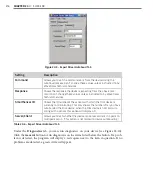
The other terminal block is reserved for alarm contacts and wiring earth ground:
˽
– Floating alarm contact
˽
– Floating alarm contact
˽
– Functional earth ground (optional)
˽
NC –
Not connected
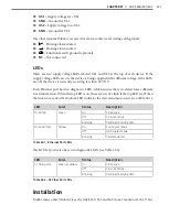
LEDs
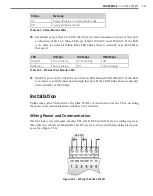
There are two supply voltage LEDs labeled US1 and US2 at the top of each device. If the
supply voltage LEDs are on, the device is being supplied with sufficient voltage; if the LEDs
are off, the device is currently receiving less than 18 VDC.
Each Ethernet port has two diagnostic LEDs, which ensure that you always have sufficient
local information. When the top LED is on, there is an active link; if the top LED is off, then
the link is not active. The bottom LED indicates the data transmission rate (see Table 26.1).
LED
Color
Status
Description
RJ-45 top
Green
On
Link active
Off
Link not active
Blinking
Sending/receiving data
RJ-45 bottom
Yellow
On
Full duplex mode
Off
Half duplex mode
Blinking
Collision detect
Table 26.1 – Ethernet Port LEDs
The SC fiber ports also have two diagnostic LEDs (see Table 26.2).
LED
Color
Status
Description
SC fiber ports
Green or yellow
On
Link active
Off
Link not active
Blinking
Sending/receiving data
Table 26.2 – SC Fiber Port LEDs
Installation
Unlike many other Click devices, the Click 340, 341 and 342 do not mount over the T-bus,
Summary of Contents for Click 100
Page 1: ...Click 100 400 Series USER GUIDE...
Page 11: ......
Page 17: ......
Page 27: ......
Page 41: ......
Page 43: ......
Page 79: ......
Page 129: ......
Page 145: ......
Page 161: ......
Page 175: ......
Page 183: ......
Page 187: ......
Page 207: ......
Page 219: ......
Page 225: ......
Page 245: ......
Page 259: ......
Page 260: ...www wavetronix com...

