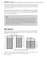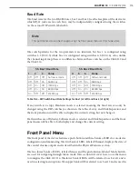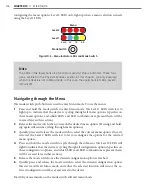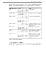
CHAPTER 10
• CLICK 112/114
119
As mentioned earlier, the Click 112/114 devices receive serial datagrams from a SmartSen-
sor. These datagrams can contain many channels of detection data. Because the devices
have fewer output channels than there are possible input datagram channels received from
the sensor, you must use the channel input map to map the desired inputs to outputs. The
Click 112 has two outputs and therefore must be mapped to two inputs; the Click 114 has
four. (If you need more than two or four channels, you’ll need to use multiple devices daisy-
chained together.)
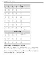
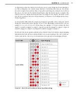
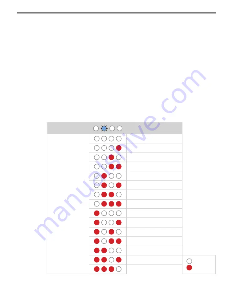
As shown in the table below, the outputs are mapped sequentially—that is, they can only be
mapped in numerically ordered groups of two or four depending on which device you are
using (1–2, 3–4, or 1–4, 5–8, etc.). If you chose, for example, 17–20 (on a Click 114), then
input 17 would be mapped to output 1, input 18 would be mapped to output 2, input 19
would be mapped to output 3, and input 20 would be mapped to output 4.
You’ll notice the menu operation labels on the Click 112 and 114 both have input mapping
information for both devices combined. Make sure you are looking at the correct informa-
tion for your device. The two sets of information are separated out and displayed below.
Level 1 LEDs
Input Mapping
Level 2 LEDs
Cancel and exit menu
Channels 1–2
Channels 3–4
Channels 5–6
Channels 7–8
Channels 9–10
Channels 11–12
Channels 13–14
Channels 15–16
Channels 17–18
Channels 19–20
Channels 21–22
Channels 23–24
Channels 25–26
LED off
LED on
Channels 27–28
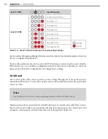
Table 10.7 – Click 112 Front Panel Menu Channel Input Map Settings
Summary of Contents for Click 100
Page 1: ...Click 100 400 Series USER GUIDE...
Page 11: ......
Page 17: ......
Page 27: ......
Page 41: ......
Page 43: ......
Page 79: ......
Page 129: ......
Page 145: ......
Page 161: ......
Page 175: ......
Page 183: ......
Page 187: ......
Page 207: ......
Page 219: ......
Page 225: ......
Page 245: ......
Page 259: ......
Page 260: ...www wavetronix com...


