92
CHAPTER 9
•
CLICK 110
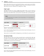
Fault latching involves how the Click 110 reacts when the flow of data from the connected
SmartSensor is interrupted. As mentioned in the Fail-safe Mode section above, if the Click
110 does not receive a datagram containing a channel that is mapped to its outputs for ten
seconds, the device will enter fail-safe mode.
In fail-safe mode, all enabled outputs will assert a detection and fault condition. The master
fault output will also assert. As long as the flow of data is reestablished within one minute,
the device will exit the mode and continue normal operation. How the device reacts when
data flow is not reestablished is determined by whether fault latch is enabled or disabled.
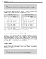
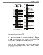
If S3:8 is on (up), fault latching is disabled. This means that if the Click 110 starts to receive
data again at any point after the one-minute mark, the device will exit fail-safe mode and
continue normal operation. If S3:8 is off (down), fault latching is enabled. In this case, if the
fault condition has existed for more than one minute, normal mode can only be restored by
rebooting (front panel reset switch, power cycle, or remote reset via outstation), even if the
device has started to receive data again.
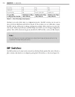
S3: Fault Latch
8
State
Off
Enable
On
Disable
Table 9.6 – DIP Switch Fault Latch Settings
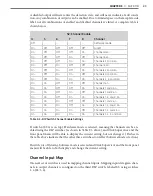
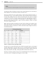
Because fault latching can only be changed using the DIP switches, there is no need (and no
option) for selecting Hardware or Software configuration modes.
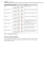
Front Panel Menu
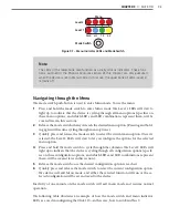
The front panel of the device features two push-buttons and four banks of LEDs for on-
device configuration and monitoring. The first two banks of LEDs, labeled Detection and
Fault, and the lower push-button, labeled Reset, are for basic monitoring and configuration
and are explained in the Physical Features section.
The two lower banks of LEDs, labeled Menu, and the first push-button, labeled Mode
Switch, are used for navigating through Menu mode. This section will cover how to use
these features and the menu to configure the Click 110.
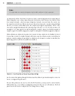
The lower bank of LEDs will be referred to as Level 1 and is used is selecting menu options.
The upper bank will be referred to as Level 2 and is used in configuring the menu options.
Summary of Contents for Click 100
Page 1: ...Click 100 400 Series USER GUIDE...
Page 11: ......
Page 17: ......
Page 27: ......
Page 41: ......
Page 43: ......
Page 79: ......
Page 129: ......
Page 145: ......
Page 161: ......
Page 175: ......
Page 183: ......
Page 187: ......
Page 207: ......
Page 219: ......
Page 225: ......
Page 245: ......
Page 259: ......
Page 260: ...www wavetronix com...


