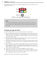
CHAPTER 10
• CLICK 112/114
117
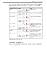
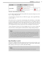
The following table illustrates an example of how the mode switch and menu indicator
LEDs are used in configuring the Click 112/114—in this case, how to autobaud bus 2.
Mode Switch Action Display
State
None
Normal operation
Press and hold
Channel map menu option displayed
Continue holding
Autobaud menu option displayed
Release
Autobaud menu option displayed
Press and release
Autobaud menu selected and first
configuration parameter displayed
(bus 1 autobaud)
Press and hold
Second configuration parameter
displayed (bus 2 autobaud)
Release
Second configuration parameter
displayed (bus 2 autobaud)
Press and release
Configuration parameter selected;
autobaud commences (will show
intermediate LED states); auto-
baud finishes and normal operation
resumes
Table 10.6 – Menu Operation Example
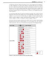
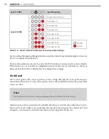
Front Panel Menu Options
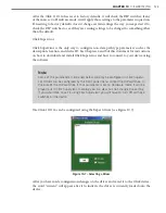
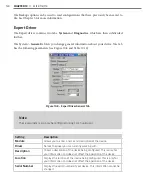
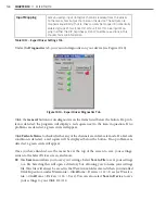
The following figure documents the menu and configuration options available from the
front panel menu. This label is also printed on the side of the circuit board (on the opposite
side from the DIP switches).
Summary of Contents for Click 100
Page 1: ...Click 100 400 Series USER GUIDE...
Page 11: ......
Page 17: ......
Page 27: ......
Page 41: ......
Page 43: ......
Page 79: ......
Page 129: ......
Page 145: ......
Page 161: ......
Page 175: ......
Page 183: ......
Page 187: ......
Page 207: ......
Page 219: ......
Page 225: ......
Page 245: ......
Page 259: ......
Page 260: ...www wavetronix com...

