background image


CHAPTER 23 

•  CLICK 301 

195

The 

System

 > 

General

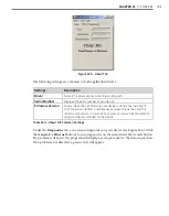
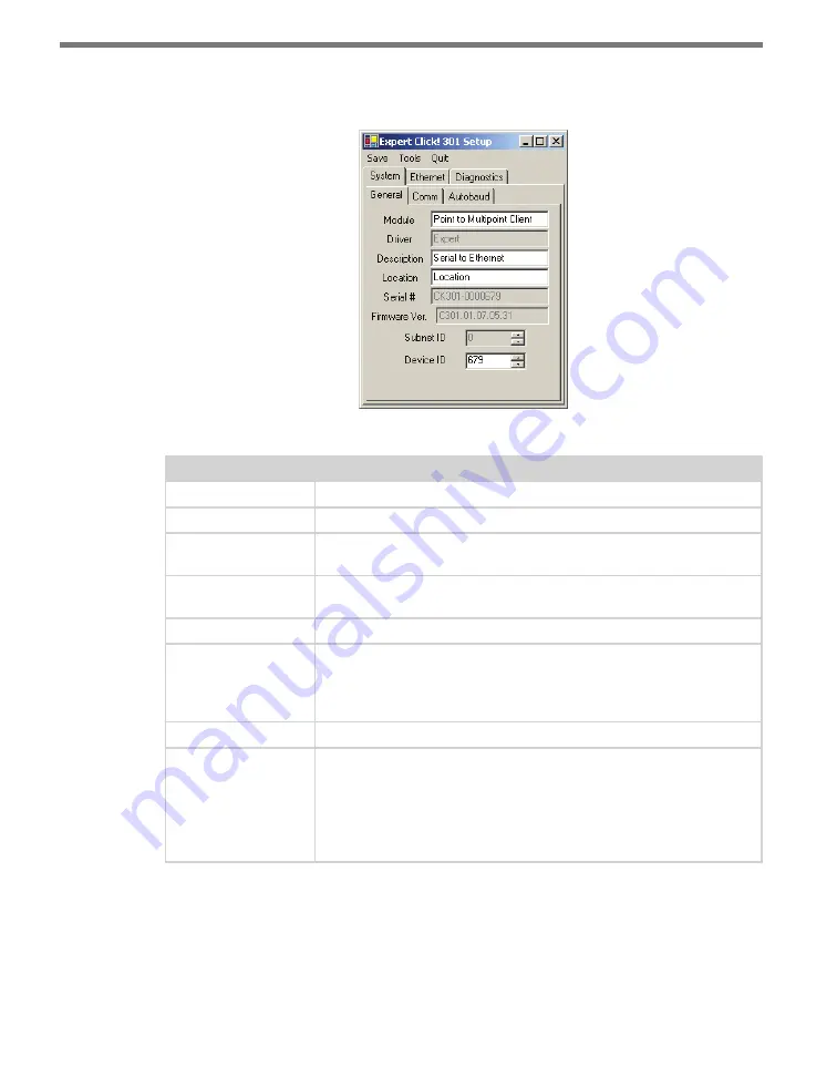
 tab combines elements of the 

Setup

 and 

About 

tabs from the other 

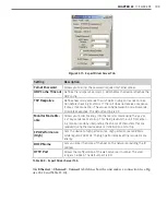
drivers (see Figure 23.7 and Table 23.5).

Figure 23.7 – Expert Driver General Tab

Setting

Description

Module

Shows the last driver (besides Expert) that was loaded onto the device. 

Driver

Names the driver you are currently working with.

Description

Shows a description of the device being configured. This is only for your 
information and does not affect the operation of the device.

Location

Displays the location of the device being configured. This is only for 
your information and does not affect the operation of the device.

Serial Number

Displays the serial number of your device.

Firmware Version

Shows the version of firmware your device currently has installed. If 
Click Supervisor detects a discrepancy between this version and the 
most current version it currently has access to, you will be prompted to 
upgrade when you connect to the device.

Subnet ID

Shows the subnet ID number. This option is currently not available.

Device ID

Gives the ID number of the device being configured, which is used to 
identify the device when you are connecting to it. By default, this num-
ber is the last five digits of the serial number, which can be found under 
the About tab or on the barcode sticker on the bottom of the device. It 
is recommended that you do not change this number unless another 
device on the network has the same ID number.

Table 23.5 – Expert Driver General Tab

The 

System

 > 

Comm 

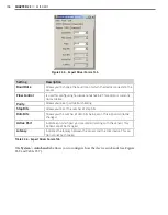
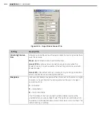
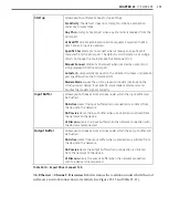
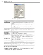
tab allows you to configure how the Click device communicates (see 

Figure 23.8 and Table 23.6).

Summary of Contents for Click 100

Page 1: ...Click 100 400 Series USER GUIDE...

Page 2: ...Click 100 400 Series USER GUIDE www wavetronix com 78 East 1700 South Provo Utah 84606 801 734 7200...

Page 3: ...CC rules which state that operation is subject to the following two conditions 1 this device may not cause harmful interference and 2 this device must accept any interference received including interf...

Page 4: ...DIN Rail 18 Mounting Click Devices 18 Wiring T buses 18 Chapter 3 Wiring the Devices 21 Working with Screw Terminal Blocks 21 RS 485 Communi cation 22 RS 232 Communication 24 Chapter 4 Installing Clic...

Page 5: ...u 92 Click Supervisor 101 Chapter 10 Click 112 114 Detector Rack Cards 107 Physical Features 108 Installation and Wiring 109 Configu ration 111 DIP Switches 112 Front Panel Menu 115 Chapter 11 Click 1...

Page 6: ...30 AC Surge Protector 179 Physical Features 180 Installation 180 Chapter 22 Click 250 Wireless Surge Protector 183 Physical Features 184 Installation 184 Chapter 23 Click 301 Serial to Ethernet Conver...

Page 7: ...sical Features 230 On device Configuration 231 Com puter Configuration 233 Chapter 28 Click 421 Serial to Bluetooth Radio 245 Physical Features 246 On device Configuration 247 Com puter Configuration...

Page 8: ...device in a par ticular series shares common elements functions etc Click 100 series Contact closure devices Click 200 series Power and surge protection devices Click 300 series Wired communication d...

Page 9: ...e installed or the software used to configure them In the event that a Click device departs from what is written in Part I that difference will be noted in that device s chapter in Part II Part II Ind...

Page 10: ...Part I Introduction to the Click Series Chapter 1 The Power Plant Chapter 2 T bus Basics Chapter 3 Wiring the Devices Chapter 4 Installing Click Supervisor Chapter 5 Using Click Supervisor...

Page 11: ......

Page 12: ...ecting Power 1 Power and surge protection are provided to your devices via the Click modules that make up what is known as the power plant see Figure 1 1 Assembling the power plant is the first step i...

Page 13: ...e from the terminal block or from the AC cord into one side of the module 4 Connect power out of the other side Note It doesn t matter which side is power in as long as the opposite end is power out C...

Page 14: ...is the AC to DC converter The Click line features several such converters The Click 201 202 204 are AC to DC power supplies that provide DC power to every Click product mounted on the DIN rail The Cli...

Page 15: ...204 Caution Make sure power to AC mains is disconnected while wiring the AC input Wiring DC Power out of the Click 201 202 204 The screw terminals on the bottom of the devices are slightly different...

Page 16: ...and operation of this unit Persons other than authorized and approved electrical technicians should NOT attempt to connect this unit to a power supply and or traffic control cabinet as there is a seri...

Page 17: ......

Page 18: ...the Click devices on the rail with only a single wiring con nection Wavetronix has two varieties of T bus connectors green connectors which conduct both power and communication and gray connectors wh...

Page 19: ...the DIN rail Note Not all Click devices use the T bus this way Some devices such as the 330 331 340 341 342 and those in the power plant snap onto the DIN rail but not onto the T bus For more informa...

Page 20: ...k follow these steps 1 Attach a male 5 screw terminal block to the left end of the T bus by aligning it with the first connector and pushing the modules together 2 Connect the black ground and red 24...

Page 21: ...l need to provide power and communication to devices in your cabinet that are not on a DIN rail or on a T bus In these cases you can connect a female 5 screw terminal block to the right side of your T...

Page 22: ...ussed This chapter will discuss another such element wiring communication through the screw terminals Working with Screw Terminal Blocks Many Click devices feature screw terminal blocks for wiring con...

Page 23: ...5 screw terminal follow these steps 1 Connect the 485 white wire from the terminal block or cable to the middle screw terminal on the 5 screw terminal block connector you re using for the T bus in que...

Page 24: ...igure 3 2 Wiring RS 485 Communication into the Click 200 Wiring RS 485 from a Click Device Several Click devices such as the 104 110 112 114 172 174 200 301 and 304 also have RJ 11 jacks for RS 485 co...

Page 25: ...rent cable or wiring system the colors of the wires used will be different To use follow the steps below 1 Connect the RTS orange wire from the cable or terminal block to the RTS screw ter minal on th...

Page 26: ...ng RS 232 Communication into the Click 200 Wiring RS 232 from a Click Device Many Click modules feature an DB 9 jack for RS 232 communication with a laptop or other such device To use simply use a str...

Page 27: ......

Page 28: ...rogrammable devices include the following Click 101 Multi sensor to contact closure module Click 104 4 channel DIN rail contact closure module Click 110 4 channel contact closure Eurocard Click 112 11...

Page 29: ...mputer included in the kit comes with Click Supervisor already installed along with sensor software If you don t have an install kit or if you want to install on a desktop computer follow the steps be...

Page 30: ...llation If you select Computer the program will go through the steps outlined in the next section Installing Click Supervisor on a PC If you select Pocket PC the program will go through the steps in t...

Page 31: ...tions are complete Figure 4 4 Shortcut Options 5 Click the View release notes when finished checkbox to view the Click Supervisor release notes The release notes contain additional information about t...

Page 32: ...e Programs application for Windows handheld devices If a handheld device is connected to the computer Add Remove Programs will immediately begin installing Click Supervisor on the handheld device If a...

Page 33: ...k 1 Click the Install Framework button 2 Click the I Agree radio button when the License Agreement appears see Figure 4 7 Figure 4 7 Microsoft NET License Agreement 3 Click Install A window will appea...

Page 34: ...re connected together by either a wired or wireless connection You can do this one of two ways If you are using an Ethernet connection you must be on the same network with the Click device Plug the Et...

Page 35: ...the T bus Accessing the Communication Screen To connect to your devices with Click Supervisor open the program by double clicking on it It will bring you to the Click Supervisor main screen see Figur...

Page 36: ...andshaking Parity Allows you to set parity error checking Stop Bits Allows you to set the number of stop bits Data Bits Allows you to set the number of data bits being sent Note The flow control parit...

Page 37: ...five digits of this number Each device on a rail must have a unique number The number it s been assigned should be unique but if it is not you can change it after connecting to the device See that de...

Page 38: ...number for the Click 301 as well as many other such devices is 10001 The default IP address is 172 16 0 13 Once a connection is made Click Supervisor will remember the information so you don t have to...

Page 39: ...asking if you d like to upgrade Each ver sion of Click Supervisor has the newest firmware for all the Click devices and when it connects to a device it will check to see if the firmware in the progra...

Page 40: ...wish to open and click OK Figure 5 6 Selecting a Backup Note The default folder to save backups in is C Program Files Wavetronix ClickHome Drivers model number User If you try to save the files elsew...

Page 41: ......

Page 42: ...lick 172 174 Chapter 13 Click 200 Chapter 14 Click 201 202 204 Chapter 15 Click 203 Chapter 16 Click 210 Chapter 17 Click 211 Chapter 18 Click 221 Chapter 19 Click 222 Chapter 20 Click 223 Chapter 21...

Page 43: ......

Page 44: ...ng 6 The Click 100 is a hot swappable contact closure module for use with the Wavetronix SmartSensor It mounts onto a DIN rail and is connected to the SmartSensor through the Click 200 surge protectio...

Page 45: ...he Mode button during configuration see the On device Configuration section of this chapter for more information Screw Terminals The contact closure outputs are wired to a controller data logger or BI...

Page 46: ...ne S1 representing the lane closest to the SmartSensor The remaining four screw terminal connections are labeled GND and are a common logic ground for all 16 contact closure outputs You must provide a...

Page 47: ...press and hold the push button until the green LED flashes four times The green LED and contact closure LEDs will flash during the auto configuration process which normally takes 5 30 seconds The aut...

Page 48: ...emulation will signal the radar s speed measurement using the time elapsed between the onset of the primary and secondary outputs but not the radar s duration measurement Instead the outputs will be...

Page 49: ...uding is successful the yellow LED will flash then the device will return to its normal state and default to the Presence mode Table 6 2 Click 100 Mode Definitions Troubleshooting The Click 100 config...

Page 50: ...t closure module that is capable of collecting lane by lane data from multiple Wavetronix SmartSensors in real time The Click 101 device is designed to collect volume and occupancy data from all midbl...

Page 51: ...the data at a particular intersection the Click 101 polls each sensor for real time lane by lane volume and occupancy data detected since the last polling period Each poll ing period typically takes...

Page 52: ...sensor does not respond after ten cycles the Click 101 will suspend data queries to that sensor for one minute After one min ute the Click 101 will retry data queries twice If those queries are unsuc...

Page 53: ...Click 101 Any devices connected to the T bus will also have connectivity over the shared RS 485 lines however when a Click 101 is being used it is expected that none of the sensors or other devices o...

Page 54: ...lick 101 suspended SmartSensor Manager for the 105 sensor only sends passcode messages on some screens so you may run into situa tions where normal polling will resume while connected to a 105 sensor...

Page 55: ...on Note It is recommended that the sensors not be connected to the T bus while program ming this device with Click Supervisor On device Configuration The Click 101 can be partially configured using th...

Page 56: ...nless you are sure that driver has been specifically de signed for your application Other drivers may inadvertently overwrite the settings on your module Once you have finished configuring your device...

Page 57: ...stalled If Click Supervisor detects a discrepancy between this version and the most current version it currently has access to you will be prompted to upgrade when you connect to the device Subnet ID...

Page 58: ...data bits being sent This option currently cannot be changed Active Port Indicates on which port you are communicating with one of the sen sors on the multi drop RS 485 bus When you communicate to mo...

Page 59: ...he sensors with which the Click device is currently communicating This only shows the number after you have autobauded the Click device when the Click device is not communicating with a sensor this op...

Page 60: ...ou select only 1 then only sensor 1 will be polled for data If you select 2 then only sensors 1 and 2 will be polled for data In other words sensors 1 X will be polled where X is the value entered in...

Page 61: ...his file will always be saved in the Wavetronix folder created when you installed Click Supervisor under Wavetronix ClickHome Drivers 101 User You can also select Save to Device to save your settings...

Page 62: ...ront Panel Menu Click Supervisor 8 The Click 104 is a 4 channel contact closure module for use with sensors that use Z4 pro tocol HD Advance and Matrix It mounts on a DIN rail for power and communicat...

Page 63: ...rew terminal for RS 232 on the top of the device Bus 2 also referred to as the control bus should be used for configuration Its associated communication port is the a 5 position connector located on t...

Page 64: ...LED indicates that the asso ciated contact is being closed this can mean either a vehicle detection or fail safe mode which will be discussed later in this chapter These indicators are dedicated to de...

Page 65: ...on the Click 104 3 If needed daisy chain multiple Click 104 devices together by utilizing both RJ 11 jacks on each device s faceplate Contact Closure Outputs Part of installing the device is wiring i...

Page 66: ...Software mode Table 8 1 Click 104 Configuration Options Configuration Modes The final row on the table refers to configuration modes Hardware mode means a par ticular parameter is set by the rotary sw...

Page 67: ...ce which incoming data channels should be mapped to which outgoing channels As mentioned earlier the Click 104 receives serial datagrams from a sensor to which it is connected These datagrams can cont...

Page 68: ...the menu to configure the Click 104 The lower bank of LEDs will be referred to as Level 1 and is used in selecting menu options The upper bank will be referred to as Level 2 and is used in configurin...

Page 69: ...LED combinations represent them will be covered later in this section 5 Release the mode switch once the desired configuration option is reached 6 Quickly press and release the mode switch to select...

Page 70: ...Baud Rate R B G Y Menu LEDs Cancel 9600 19200 38400 57600 1 2 3 4 Bus 2 Baud Rate R B G Y Menu LEDs Cancel 9600 19200 38400 57600 1 2 3 4 Autobaud R B G Y Menu LEDs Cancel Bus 1 Bus 2 1 2 3 4 Reset to...

Page 71: ...lly that is they can only be mapped in numerically ordered groups of four 1 4 5 8 etc If you set the switch to 3 for 9 12 then input 9 would be mapped to output 1 input 10 would be mapped to output 2...

Page 72: ...configure this parameter As each baud rate is attempted the Level 2 LEDs will sequence with a single LED illumi nated from LED 1 4 If the Click 104 is successful in communicating with a SmartSensor it...

Page 73: ...Settings The final option that comes up in the menu is Reset to Default Settings To select this func tion release the mode switch when the red LED starts flashing Note Resetting to default settings ca...

Page 74: ...ad and install Click Supervisor and how to connect to your device using the software Note Some of the parameters mentioned below can only be configured in Click Supervisor Others can be configured by...

Page 75: ...8 7 Expert Driver General Tab Note These parameters can only be configured using Click Supervisor Setting Description Module Allows you to enter a name and description of the device Driver Names the...

Page 76: ...the device It is recommended that you do not change this number unless another device on your network has the same ID number Table 8 8 Expert Driver General Tab The System Settings tab lets you confi...

Page 77: ...igure 8 9 Figure 8 9 Expert Driver Diagnostics Tab Click the General button to run diagnostics on the items listed below the button If a prob lem is detected the program will display a red square next...

Page 78: ...device to the settings with which it was shipped Restore will restore the driver to the settings cur rently saved on the Click 104 erasing any unsaved changes Upgrade can be used to manually upgrade...

Page 79: ......

Page 80: ...a MIDAS outstation when used with Wa vetronix SmartSensors This card plugs directly into an outstation and reports four channels of detection Because the Click 110 has two independent serial buses it...

Page 81: ...through a serial data con verter Typically one bus is used to report vehicle data and the other is used for configuration As both buses are identical it does not matter which is used for data or confi...

Page 82: ...de two rows of LEDs see Figure 9 3 The lower row con tains Level 1 indicators while the upper row contains Level 2 indicators Each level consists of four LEDs numbered 1 4 left to right Level 1 LEDs d...

Page 83: ...he following steps to install and wire Click 110 devices 1 If you re using hardware configuration set all DIP switches before installing Click 110 devices this will be covered in the DIP Switches sect...

Page 84: ...ection A28 No connection A29 Reset A30 No connection A31 No connection A32 No connection Description Pin Channel 1 fault normally closed B1 Channel 1 common B2 Channel 1 fault common B3 Master fault n...

Page 85: ...ection A28 No connection A29 Reset A30 No connection A31 No connection A32 No connection Description Pin Channel 1 fault normally open B1 Channel 1 common B2 Channel 1 fault common B3 Master fault nor...

Page 86: ...e device will enter fail safe mode In fail safe mode all enabled outputs will assert a detection and fault condition The master fault output will also assert How the device gets out of fail safe mode...

Page 87: ...e set to Hardware mode the DIP switches will be used to change configuration options If the switches are set to Soft ware mode the front panel menu and Click Supervisor will be used to change configur...

Page 88: ...ch Each parameter except fault latch and outstation mode has a way to pick between Hard ware Software modes If Software mode is selected the parameter must be configured using the front panel menu or...

Page 89: ...1 left and Bus 2 right As these tables show if the switches are in any configuration besides the ones laid out in the first few rows of these tables that bus will default to 9600 bps If switch 1 5 is...

Page 90: ...n Off On On Channels 1 3 and 4 on On On On Off Off Channels 1 and 2 on On On On Off On Channels 1 2 and 4 on On On On On Off Channels 1 2 and 3 on On On On On On Channels 1 2 3 and 4 on Table 9 3 DIP...

Page 91: ...are required any contact closure output can be disabled A dis abled output will never enter the detection state and will never indicate a fault condition Depending on whether each channel is enabled o...

Page 92: ...et to work with a Siemens brand outstation S3 Outstation Mode 6 State Off Peek On Siemens Table 9 5 DIP Switch Outstation Mode Settings Note In Peek mode the Isolated fault output channels are N C in...

Page 93: ...condition has existed for more than one minute normal mode can only be restored by rebooting front panel reset switch power cycle or remote reset via outstation even if the device has started to rece...

Page 94: ...ycling through menu options 3 Quickly press and release the mode switch to select the current menu option Once it s selected the Level 2 LEDs will start to let you configure the options for the select...

Page 95: ...ayed bus 1 autobaud Press and hold Second configuration parameter displayed bus 2 autobaud Release Second configuration parameter displayed bus 2 autobaud Press and release Configuration parameter sel...

Page 96: ...et to Default Settings Cancel and Exit Menu Outstation Support Settings Fault Latch Channel Enable Autobaud Settings Baud Rate Setting for Bus 1 Baud Rate Setting for Bus 2 Press and hold Mode Switch...

Page 97: ...would be mapped to output 4 If fewer than four outputs are required any contact closure output can be disabled covered later in this section A disabled output will never enter the detection state and...

Page 98: ...onfigure this parameter As each baud rate is attempted the Level 2 LEDs will sequence with a single LED illumi nated from LED 1 4 If the Click 110 is successful in communicating with a SmartSensor it...

Page 99: ...ee the earlier Navigating through the Menu and the Menu Operation Example sections for how to configure this parameter Because this parameter can also be set by the DIP switches you may need to ensure...

Page 100: ...Channels 1 3 and 4 on Channels 1 and 2 on Channels 1 2 and 4 on Channels 1 2 and 3 on Channels 1 2 3 and 4 on LED off LED on Cancel and exit menu Table 9 11 Front Panel Menu Channel Enable Settings N...

Page 101: ...h enabled LED off LED on Fault latch disabled Table 9 12 Front Panel Menu Fault Latch Settings See the earlier Navigating through the Menu and the Menu Operation Example sections for how to view this...

Page 102: ...vel 2 LEDs Reset to default settings LED off LED on Cancel and exit menu Table 9 14 Front Panel Menu Reset to Default Settings See the earlier Navigating through the Menu and the Menu Operation Exampl...

Page 103: ...can be configured using the Expert driver see Figure 9 9 Figure 9 9 Selecting a Driver After you have made configuration changes on the driver and saved it to the Click device the word current will a...

Page 104: ...nnot be changed Firmware Version Shows the version of firmware your device currently has installed If Click Supervisor detects a discrepancy between this version and the most current version it curren...

Page 105: ...nput Mapping Lets you assign input datagram channels received from the sensor to the device s four output channels The outputs are mapped sequen tially that is they can only be mapped in numerically o...

Page 106: ...re next to the item in question If no problems are detected a green circle will appear Click Fault Status to check whether any of the channels are indicating a fault condition If a fault status is det...

Page 107: ...r device to the settings with which it was shipped Restore will restore the driver to the settings cur rently saved on the Click 110 erasing any unsaved changes Upgrade can be used to manually upgrade...

Page 108: ...lick 112 and 114 are 2 channel and 4 channel contact closure cards that can be used with the SmartSensor Matrix Advance or HD These cards plug into any standard detector rack card slot and can be conn...

Page 109: ...uld be used to report vehicle data and bus 2 should be used for configuration Having one bus dedicated to each function leads to optimum Click 112 114 performance On certain newer devices the buses ar...

Page 110: ...onsists of four LEDs numbered 1 4 left to right Level 1 LEDs the multicolored row display which menu item is active These Level 1 LEDs are dual purpose each indicating both menu selection as well as a...

Page 111: ...VDC 3 No connection C No connection 4 No connection D No connection 5 No connection E No connection 6 No connection F Channel 1 output 7 Channel 1 status output H Channel 1 output 8 No connection J No...

Page 112: ...s Yes Description No No Yes Location No No Yes Device ID No No Yes To use this configuration feature Hardware mode Software mode Software mode Table 10 2 Click 112 114 Configuration Options The final...

Page 113: ...tagrams from the connected SmartSensor These data grams must be mapped to device outputs covered in the next section If the Click 112 114 does not receive a datagram describing the device s channels f...

Page 114: ...rams can contain many channels of detection data Because the devices have fewer output channels than there are possible input datagram channels received from the sensor you must use the channel input...

Page 115: ...4 Channel Off Off Off Off Software mode Off Off Off On 1 4 Off Off On Off 5 8 Off Off On On 9 12 Off On Off Off 13 16 Off On Off On 17 20 Off On On Off 21 24 Off On On On 25 28 Table 10 4 Click 114 D...

Page 116: ...IP Switch Baud Rate Settings for Bus 1 at left and Bus 2 at right If any switch is on up Hardware mode is selected meaning the baud rate can only be changed using the DIP switches as shown in the tabl...

Page 117: ...esent them will be covered later in this section 2 Release the mode switch when you reach the desired menu option Pressing and hold ing again will resume cycling through menu options 3 Quickly press a...

Page 118: ...selected and first configuration parameter displayed bus 1 autobaud Press and hold Second configuration parameter displayed bus 2 autobaud Release Second configuration parameter displayed bus 2 autoba...

Page 119: ...ting that particular menu option from the Level 1 LEDs the Level 2 LEDs will display the configuration option set in the DIP switches but will not allow you to modify the set ting When you have finish...

Page 120: ...roups of two or four depending on which device you are using 1 2 3 4 or 1 4 5 8 etc If you chose for example 17 20 on a Click 114 then input 17 would be mapped to output 1 input 18 would be mapped to...

Page 121: ...he DIP switches are set to Software configuration mode if they are set to Hardware the front panel menu will be able to display but not change these settings Autobaud The second option that comes up w...

Page 122: ...d stored to the baud rate detected during the autobaud process If the autobaud fails all four Level 2 LEDs will light up for a few seconds and then the menu will return to normal operation with the ba...

Page 123: ...ange these settings Reset to Default Settings The final option that comes up in the menu is Reset to Default Settings To select this func tion release the mode switch when the red LED starts flashing...

Page 124: ...download and install Click Supervisor and how to connect to your device using the software Note Some of the parameters mentioned below can only be configured in Click Supervi sor Others can be configu...

Page 125: ...10 8 Expert Driver General Tab Note These parameters can only be configured using Click Supervisor Setting Description Module Allows you to enter a name and description of the device Driver Names the...

Page 126: ...n the barcode sticker on the bottom of the device It is recommended that you do not change this number unless another device on your network has the same ID number Table 10 12 Expert Driver General Ta...

Page 127: ...y a red square next to the item in question If no problems are detected a green circle will appear Click Failsafe Status to check whether any of the channels are in fail safe mode If a fail safe condi...

Page 128: ...our device to the settings with which it was shipped Restore will restore the driver to the settings cur rently saved on the Click 112 114 erasing any unsaved changes Upgrade can be used to manually u...

Page 129: ......

Page 130: ...In this chapter Physical Features Installation 11 The Click 120 121 provide an interface between Click contact closure devices and signaling systems Figure 11 1 The Click 120 Click 120 121 Relay 11...

Page 131: ...ont of the device is an LED marked 24 V This LED will light up when the coil side is receiving 24 VDC in meaning there is a current from the contact closure mod ule and the contact side of the Click 1...

Page 132: ...As this is the power that will run the load or loads it needs to be the type of current and the voltage that the loads use 5 Wire your loads into the terminals marked 12 and 14 If you are using one l...

Page 133: ...fic controller 4 Wire from the 14 terminal on the contact side of each relay to its corresponding light in the traffic signal for example make sure the relay that is wired to the contact closure outpu...

Page 134: ...172 2 channel and Click 174 4 channel are contact closure cards used with Wavetronix SmartSensors These cards plug into any standard detector rack card slot and can be connected directly to the Smart...

Page 135: ...ly when the Settings switch is in position 2 Lane The face plate also features the Settings switch which allows you to switch between the two programming states Mode and Lane and run the mode you have...

Page 136: ...ltage output as opposed to contact closure output By default the DIP switch is down disabled because most standard controllers and bus interface units require a contact closure output Do NOT put the D...

Page 137: ...n will simply signal the radar s duration measurement no speed information PU Pulse Outputs contact closures for single loop or dual loop emulation Dual loop emulation will signal the radar s speed me...

Page 138: ...f a traditional dual loop system In a traditional system a vehicle would travel over the primary detector and then the secondary detector see Figure 12 4 Primary Detector Secondary Detector Traffic Di...

Page 139: ...nnel lane Output Channel 2 Secondary Channel 1r 55 Figure 12 6 Dual Loop Emulation System After you have configured the sensor using SmartSensor Manager assign lane numbers to each lane The Click 172...

Page 140: ...f the four supported RS 485 baud rates 9600 19200 38400 and 57600 bps and then query the sensor to set the loop spacing parameters The sensor will automatically be configured to push event or actuatio...

Page 141: ...2 Lane to check the output channel assignments 3 Push the Channel button to view the current channel assignments Each time you press the Channel button the output channel number will briefly flash fol...

Page 142: ...above daisy chain procedure is followed starting from that card Figure 12 7 Cards Daisy chained Together Note The last Click 172 174 card s RJ 11 jack will have an unconnected jack However if the cabl...

Page 143: ...or all lanes To select this option press the Channel button until AL is displayed The card will now start displaying speeds in miles per hour or kilometers per hour depend ing upon your sensor configu...

Page 144: ...u may need to complete the following steps to clear the lane mapping memory buffer 1 Move the Settings switch to position 1 Mode 2 Once the display shows Pr press and release the Channel button 3 Pres...

Page 145: ......

Page 146: ...tions suppressing power surges for DC power half duplex RS 485 communication and full duplex RS 232 communication with CTS and RTS The Click 200 can also be used to protect any device from surges from...

Page 147: ...and the sensor or the sensor block which is in turn connected to the sensor They will be discussed in greater detail in the Installation section of this chapter There are also two other ways to wire...

Page 148: ...Power Connections The Click 200 receives power from the T bus via the T bus connection on the back of the module Additionally if the power supply is not wired directly into the T bus power can be conn...

Page 149: ...sor 120 VAC Main Traffic Cabinet Pole Mount Traffic Cabinet Both ends of the homerun cable connect to the UNPROTECTED side of the surge modules Figure 13 3 Standard SmartSensor Installation Using Home...

Page 150: ...ectly wire to earth ground 1 Connect the grounding wire from either the DIN rail or a GND screw terminal on the UNPROTECTED side of the Click 200 to the lug bolt on the inside of the pole mount box 2...

Page 151: ...ctions 1 Check the RS 232 connection by plugging a straight through RS 232 cable between a laptop and the DB 9 connector on the Click 200 2 Launch SmartSensor Manager and connect via a serial connecti...

Page 152: ...providing reliable DC power to the rest of the cabinet unless a Click 203 is used see Chapter 1 A Click 201 provides 1 A of power and is capable of powering a single Wavetronix Smart Sensor a Click 2...

Page 153: ...204 modules also have a green activity indicator light marked DC OK on the faceplate This light glows steadily when the module is working properly but will go out if the power supply is interrupted o...

Page 154: ...black L Neutral white N Table 14 1 Wiring AC Power In Figure 14 3 Wiring AC Power into the Click 201 202 204 Note The NC screw terminals found in the Click 201 and 202 are not connected internally Con...

Page 155: ...14 CLICK 201 202 204 Figure 14 4 Wiring DC Power out of the Click 201 202 204 Note Do not wire out of the DC OK terminal it supplies only 20 mA and should only be used to monitor the status of the po...

Page 156: ...pted power supply and battery keeping power supplied to your equipment even when the external power source goes out The UPS con verts AC power to DC with a 2 A output and the battery will keep a Smart...

Page 157: ...rew terminals for wiring to the battery and the block on the left has seven screw terminals for DC out among other things Wiring the device will be discussed later in the chapter The screw terminals a...

Page 158: ...he AC input Wiring out of the UPS Module Terminal Connection DC out red DC out black Alarm Active switching output see Signaling Outputs section Bat Mode Active switching output see Signaling Outputs...

Page 159: ...the hole and twist until the arrow in the screw head is pointing to the time you want The switch has times from half a minute to thirty minutes or you can set it to remain on continuously by turning t...

Page 160: ...UBAT 20 4 V DC LED off LED on battery mode battery charge output 0 V LED on output 24 V Rechargeable battery test negative LED on LED off battery mode battery charge output 0 V LED on output 24 V Buf...

Page 161: ......

Page 162: ...to interrupt an electric current under overload conditions The breaker is trip free and can be easily reset after a current interruption by pushing the reset button Use the Click 210 as part of your...

Page 163: ...h side for wiring power It also fea tures a reset button on top that can be used to reset the breaker after a current interruption Installation Connect the line black wire from the AC terminal block o...

Page 164: ...ices pow ered through an AC power plug The outlet snaps onto a DIN rail and is wired through twin terminal blocks attached to the power plant If you are using a Click 211 the power plant configuration...

Page 165: ...so an LED located on the front of the module this LED lights up when the Click 211 is working properly Installation Installing the Click 211 involves a slight change in how your installation s power p...

Page 166: ...black wires respectively 5 Terminate the white or neutral wire into one of the ports on the first twin terminal block Terminate the black or line wire into one of the ports on the second twin termi na...

Page 167: ...set of ports on the two twin terminal blocks following the coloring of the wires attached to each block 3 Snap the Click 211 onto a DIN rail within reaching distance of the device to be plugged in Th...

Page 168: ...input to protect your equipment from surges on the power lines Figure 18 1 The Click 221 This device is used if your device has a DC power input and therefore does not need the Click power plant modu...

Page 169: ...nit as a reference in the field The faceplate has an LED used for monitoring the device if the LED is on the device has power and the surge protection is functional Installation To install and wire th...

Page 170: ...lectrical surges con ducted along underground cables from damaging the cabinet equipment The power and RS 485 serial connections on the device are protected from these incoming surges It can be used w...

Page 171: ...or 2 detection calls Lowest jack dedicated communications for sensor 1 detection calls The back of the Click 222 features a 5 position connector that plugs into a T bus connector and provides power an...

Page 172: ...ED does not indicate data received on the A or B ports Installation The Click 222 is commonly used with the SmartSensor Matrix and SmartSensor 6 conduc tor cable the steps that follow in this section...

Page 173: ...ble from sensor 1 to the middle pluggable screw terminal block connect the blue and white striped wire to the screw terminal marked 485C Connect the blue wire to the screw terminal marked 485C 4 If yo...

Page 174: ...rs in your system repeat steps 1 3 for all remaining rack cards Figure 19 4 Wiring the Click 112 114 Rack Cards 5 Connect a patch cord from one of the Click 222 bridge ports to bus 2 of the rack cards...

Page 175: ......

Page 176: ...aging connected equipment It protects one DC power and two RS 485 serial connec tions from these incoming surges which are usually caused by lightning strikes and carried along underground cables The...

Page 177: ...features a 5 position connector that plugs into a T bus connector and passes power and communication from the Click 223 to the rest of the T bus and vice versa This connector is only connected to the...

Page 178: ...ds on your installation If you ve got an un derground cable run you ll put a Click 223 on each end and connect the ends of the cable to the UNPROTECTED side of each device If you re connecting to a se...

Page 179: ...d wire into the screw terminal marked DC and the black wire into DC 5 Wire the drain into any screw terminal marked GND 6 Connect a 14 AWG wire between either of the terminals marked PE to a grounded...

Page 180: ...In this chapter Physical Features Installation 21 The Click 230 provides up to 10 kA 8 20 S of surge protection per AC input line Figure 21 1 The Click 230 Click 230 AC Surge Protector 21...

Page 181: ...diodes SAD high powered current handling gas dis charge tubes GDT and series decoupling elements Physical Features The Click 230 has eight active screw terminal connections The module is wired in thr...

Page 182: ...screw terminals 1 and 3 respectively also on the side marked IN 3 Connect the outgoing neutral and power wires to screw terminals 2 and 6 respectively on the side marked OUT Terminals 3 and 4 are dire...

Page 183: ......

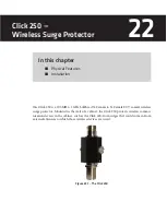
Page 184: ...coaxial wireless surge protector Mounted in the wall of a cabinet the Click 250 protects wireless commu nication devices in the cabinet such as the Click 400 from surges that could come in from extern...

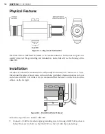
Page 185: ...wall usually the bottom of a cabinet in a 5 8 hole Wavetronix fiberglass cabinets come with such holes predrilled aluminum cabinets do not and a hole will need to be drilled It is recommended that the...

Page 186: ...d of the Click 250 then insert that end into the hole in the side of the cabinet 4 Push the provided rubber washer over the bulkhead end which should now be on the outside of the cabinet Reattach the...

Page 187: ......

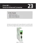
Page 188: ...hernet converter changes half duplex two wire RS 232 and RS 485 communication to Ethernet and vice versa Use this device in a cabinet to transfer data from a sensor to your computer or traffic operati...

Page 189: ...nal block that features 485 one 485 and two ground screw terminals for wiring RS 485 communication This screw terminal block can be removed for easy preinstallation wiring It will not be necessary to...

Page 190: ...out of any mode and return the unit back to normal operation Table 23 1 and the fol lowing sections describe the different operating modes Mode LED Definition Autobaud Green solid To autobaud the Clic...

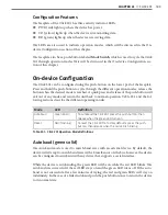
Page 191: ...pplication To reset the Click 301 to factory defaults release the push button when the red LED begins flashing The red LED should blink slowly then the green and yellow LEDs will flicker When the red...

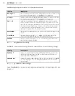
Page 192: ...driver and saved it to the Click device the word current will appear after that driver to indicate the driver that is currently loaded onto the device Note Some settings appear on multiple drivers Cha...

Page 193: ...e ID number Baud Rate Allows you to change the baud rate at which the device connects to the sensor IP Address Lets you view and change the IP address currently assigned to the device Each Click 301 d...

Page 194: ...Supervisor detects a discrepancy between this version and the most current version it currently has access to you will be prompted to upgrade when you connect to the device Table 23 4 About Tab Common...

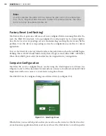
Page 195: ...the next time you power the device down The Tools menu contains five options for working with your device Reset System power cycles your device while Reset Factory Default restores your device to the...

Page 196: ...ware Version Shows the version of firmware your device currently has installed If Click Supervisor detects a discrepancy between this version and the most current version it currently has access to yo...

Page 197: ...error checking Stop Bits Allows you to set the number of stop bits Data Bits Shows you the number of data bits being sent This option cannot be changed Active Port Indicates on which port you are com...

Page 198: ...ed to by Wavetronix Technical Services SmartSensor ID Shows the ID number of the sensor with which the Click device is currently communicating This only shows the number after you have autobauded the...

Page 199: ...twork Remote IP Allows you to enter the IP address of the Click 301 that the Click 301 you re configuring should connect to Each Click 301 defaults to a remote IP address of 172 16 0 14 Remote TCP Por...

Page 200: ...to disable entry into the monitor mode using the yyy or xx1 key sequence at startup This field prevents the unit from enter ing monitor mode by interpreting the stream of characters that are received...

Page 201: ...Modem mode Accept All is the default setting and accepts any incoming connection when a connection is not already established Response Lets you set character response When this is set to Character a s...

Page 202: ...t accepts AT style modem commands and handles the modem signals correctly Input Buffer Allows you to choose circumstances under which the input buffer will be flushed On Active clears the input buffer...

Page 203: ...the serial port CTRL D Disconnect Drops the connection when Ctrl D or Hex 04 is detected Both Telnet Com Port Cntrl and Check EOT Ctrl D must be enabled for Disconnect with EOT to function properly C...

Page 204: ...Send Characters Lets you enter up to two characters in hexadecimal If the module receives a character on the serial line that matches one of these characters it sends the character immediately along w...

Page 205: ...ver Hostlist Tabs Setting Description Hostlist Enable Enables the use of the host list Retry Counter Lets you set the number of times the module should attempt to retry connecting to the host list Ret...

Page 206: ...d Click Supervisor under Wavetronix ClickHome Drivers 301 User You can also select Save to Device to save your settings to your Click 301 Note If you do not save your settings to your Click 301 they w...

Page 207: ......

Page 208: ...guration 24 The Click 304 converts half duplex RS 232 communication to RS 485 communication and vice versa The Click 304 improves serial communications and also extends the capabilities of a serial ne...

Page 209: ...o grounds for wiring RS 485 communication This screw terminal block can be removed for easy preinstallation wiring It will not be necessary however to wire RS 485 through the screw terminal block if t...

Page 210: ...f any mode and return the unit back to normal operation Table 24 1 and the fol lowing sections describe the different operating modes Mode LED Definition Autobaud Green solid To autobaud the Click 304...

Page 211: ...ce the device is responding restore the configuration needed for its current application Computer Configuration The Click 304 can be configured more exactly using the Click Supervisor software See Cha...

Page 212: ...all other drivers it appears on The Backups option can be used to read configurations that have previously been saved to file See Chapter 5 for more information SmartSensor Driver The SmartSensor dri...

Page 213: ...304 see Figure 24 5 and Table 24 3 Figure 24 5 SmartSensor Driver About Tab Settings Description Driver Names the driver you are currently working with Serial Number Displays the serial number of your...

Page 214: ...your settings to your Click 304 they will be lost the next time you power the device down The Tools menu contains five options for working with your device Reset System power cycles your device while...

Page 215: ...ration of the device Serial Number Displays the serial number of your device Firmware Version Shows the version of firmware your device currently has installed If Click Supervisor detects a discrepanc...

Page 216: ...t parity error checking Stop Bits Allows you to set the number of stop bits Data Bits Shows you the number of data bits being sent This option currently cannot be changed Active Port Indicates on whic...

Page 217: ...s currently communicating This only shows the number after you have autobauded the Click device when the Click device is not communi cating with a sensor this option will display a 0 Server Client All...

Page 218: ...r settings to your Click 304 Note If you do not save your settings to your Click 304 they will be lost the next time you power the device down The Tools menu contains five options for working with you...

Page 219: ......

Page 220: ...ernet network expansion at the field level The switches offer transmission speeds of 10 100 1000 Mbps The RJ 45 ports offer auto crossing and auto negotiation functionality The fiber optic ports in th...

Page 221: ...power supply US2 and GND and alarm notices R1 and R2 Ethernet Fiber Optic Ports The Click 330 and 331 feature the following physical Ethernet and fiber options Click 330 Unmanaged switch with eight RJ...

Page 222: ...CT On or blinking Off On or blinking Table 25 2 Ethernet Port Monitor LEDs The fiber ports on the Click 331 each have an LED labeled 1000 LNK ACT If this LED is on there is a valid connection through...

Page 223: ...es into the ports on the Click 331 Switching Characteristics Store and Forward All data telegrams that are received by the switch are saved and their validity checked In valid or faulty data packets 1...

Page 224: ...ng Ethernet packets that have already been assignent a priority level by a managed switch or other In cases of heavy traffic packets with a priority 4 7 are considered high priority and processed befo...

Page 225: ......

Page 226: ...omplete network management via SNMP and have an integrated Web server for comprehensive configuration and diagnostic mechanisms This chapter covers only the physical features and installation of the d...

Page 227: ...ports Click 341 Managed switch with four RJ 45 ports and two multimode SC ports Click 342 Managed switch with four RJ 45 ports and two single mode SC ports Serial Configuration Port The top of the th...

Page 228: ...LEDs which ensure that you always have sufficient local information When the top LED is on there is an active link if the top LED is off then the link is not active The bottom LED indicates the data...

Page 229: ...ed US1 3 Attach a wire for DC black is standard to the screw terminal marked GND 4 Attach the other end of these two wires to a DC power source In a traffic installation with other Click modules the b...

Page 230: ...orts and one RS 232 port which are active at all times The unit also auto detects the serial settings of a Smart Sensor network for quick and easy installation Supporting baud rates of 9600 bps to 115...

Page 231: ...w terminal block can be removed for easy preinstallation wiring It will not be necessary however to wire RS 485 through the screw terminal block if the device is connected to a T bus with uninterrupte...

Page 232: ...on will exit out of any mode and return the unit back to normal operation Table 27 1 and the fol lowing sections describe the different operating modes Mode LED Definition Autobaud Green solid To auto...

Page 233: ...rns on solid The client device will have a solid red LED 3 Watch the client to be sure it has found a server if the device finds a server on the same channel the blue LED will be solid If the blue LED...

Page 234: ...to work in specific applications Use the list below to find the appropriate driver for your application Client If you intend to connect multiple clients to a single server use the Client driver Serve...

Page 235: ...al fields and settings so the section that follows will use images of just one of those drivers as an example Under the Setup tab you can change the settings affecting the setup of the device and sens...

Page 236: ...ommended that each system be on a different channel since the ranges on these devices extend for miles and sharing the same channel with another location could result in interference Tx Power 1W Max A...

Page 237: ...e 27 6 Diagnostics Tab The RSSI display will show the relative RSSI strength of the radio which is useful for detect ing a low signal If a low RSSI strength is shown the user can boost the transmit po...

Page 238: ...vice Hex View changes the view of certain settings in the driver to hexadecimal Clicking the Quit menu exits the driver and returns you to the Click Supervisor main page Expert Driver The Expert drive...

Page 239: ...t available Device ID Gives the ID number of the device being configured which is used to identify the device when you are connecting to it By default this number is the last five digits of the serial...

Page 240: ...ss Don t change these values unless instructed to by Wavetronix Technical Services Response Shows the response the device is expecting from the above com mand Don t change these values unless instruct...

Page 241: ...et up as a client select Address Broadcast if the device is set up as a server select Address RF Delivery Allows you to send to a specific address or broadcast to all radios If the device is set up as...

Page 242: ...nnel Allows you to synchronize channels with other servers Sync Channel Allows you to choose the channel number to synch to This number must be lower than the RF channel DES Encryption Allows you to e...

Page 243: ...device see Figure 27 13 Click the General or 900 MHz buttons to run diagnostics on the items listed below each button If a problem is detected the program will display a red square next to the item in...

Page 244: ...e Reset Factory Default restores your device to the settings with which it was shipped Restore will restore the driver to the settings cur rently saved on the Click 400 erasing any unsaved changes Upg...

Page 245: ......

Page 246: ...21 serial to Bluetooth radio converts half duplex two wire RS 232 and 485 com munication to Bluetooth and vice versa Use this device in a cabinet to transfer data from a sensor to your computer via a...

Page 247: ...ng RS 485 communication It will not be necessary however to wire RS 485 through the screw terminal block if the device is con nected to a T bus with uninterrupted RS 485 communication The second block...

Page 248: ...n be configured using the push button on the lower part of the faceplate Press and hold the push button to cycle through the different operation modes release the button when the desired mode is reach...

Page 249: ...LED will come on to indicate that there is a connection to the external Bluetooth device you are connected to If the connection is no longer valid the blue LED will never come on and the device LEDs...

Page 250: ...e the SmartSen sor driver To see advanced settings use the Expert driver This driver which exposes every available field for the Click 421 should only be used under the direction of Wavetronix Technic...

Page 251: ...gured This is only for your information and does not affect the operation of the device Device ID Gives the ID number of the device being configured which is used to identify the device when you are c...

Page 252: ...ntly has access to you will be prompted to upgrade when you connect to the device Bluetooth Name Shows the name of the device which is broadcast with the Bluetooth signal This name can be changed in t...

Page 253: ...21 they will be lost the next time you power the device down The Tools menu contains five options for working with your device Reset System power cycles your device while Reset Factory Default restore...

Page 254: ...Firmware Version Shows the version of firmware your device currently has installed If Click Supervisor detects a discrepancy between this version and the most current version it currently has access t...

Page 255: ...ity error checking Stop Bits Allows you to set the number of stop bits Data Bits Shows you the number of data bits being sent This option cannot be changed Active Port Indicates on which port you are...

Page 256: ...s SmartSensor ID Shows the ID number of the sensor with which the Click device is currently communicating This only shows the number after you have autobauded the Click device when the Click device is...

Page 257: ...se of a password on the signal Table 28 7 Expert Driver Bluetooth Tab Note If you decide to password protect your Click 421 be sure to keep a good record of the password you choose Wavetronix is not a...

Page 258: ...so select Save to Device to save your settings to your Click 421 Note If you do not save your settings to your Click 421 they will be lost the next time you power the device down The Tools menu contai...

Page 259: ......

Page 260: ...www wavetronix com...

Reviews: