62
CHAPTER 4
•
CLICK 104
Physical Features
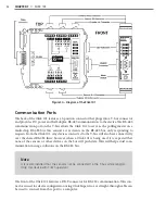
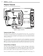
The Click 104 has the following physical features.
T-Bus
Connector
RS-232 Connector
Outputs 1-2 Connector
Mode Switch
RS-485
Connector
LED Indicators
Rotary Switch
Outputs 3-4 Connector
FRONT
TOP
RS-232
3-4
1-2
LEDs
RS-485
Bus 2
Control
Contact
Closures
+DC
-DC
+485
-485
GND
Bus 1
Data
Bus 1
Data
104
Click
Mode
Switch
Rotary
Switch
Figure 8.2 – Diagram of Click 104
Communication Ports
The Click 104 has two independent serial communications buses. Bus 1, also referred to
as the data bus, should be used to report vehicle data; its associated communication ports
consist of two RJ-11 jacks, for RS-485, on the faceplate and one screw terminal, for RS-232,
on the top of the device.
Bus 2, also referred to as the control bus, should be used for configuration. Its associated
communication port is the a 5-position connector, located on the back of the Click 104, that
plugs into a T-bus connector and provides power and RS-485 communication to the device.
It also passes RS-485 communication from the Click 104 to all other devices on the T-bus.
Contact Closure Outputs
The contact closure outputs should be wired to a controller, data logger or BIU (Bus In-
terface Unit) using the pluggable screw terminals on the bottom of the Click 104. There
are two screw terminal blocks; the one closer to the faceplate has outputs 1 and 2, and the
farther one has outputs 3 and 4. Each output consists of two terminals, one + and one –.
The screw terminal connectors can also be unplugged from the Click 104 allowing you to
Summary of Contents for Click 100
Page 1: ...Click 100 400 Series USER GUIDE...
Page 11: ......
Page 17: ......
Page 27: ......
Page 41: ......
Page 43: ......
Page 79: ......
Page 129: ......
Page 145: ......
Page 161: ......
Page 175: ......
Page 183: ......
Page 187: ......
Page 207: ......
Page 219: ......
Page 225: ......
Page 245: ......
Page 259: ......
Page 260: ...www wavetronix com...

