A00477
Cover
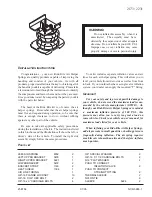
Atmosphere
Platinum
Electrode
Solid Electrolyte
(Zirconia Element)
Platinum
Electrode
Heater
Coating (Ceramic)
Exhaust Gas
(V)
4.0
3.8
3.6
3.4
3.2
3.0
2.8
2.6
17
Air-Fuel Ratio
2.4
16
15
12
14
13
19
18
ECM
Monitored
A/F Sensor V
oltage
DI-42
-
DIAGNOSTICS
ENGINE
196
Author:
Date:
2001 SIENNA (RM787U)
DTC
P0125
Insufficient Coolant Temp. for Closed Loop
Fuel Control
CIRCUIT DESCRIPTION
To obtain a high purification rate for the CO, HC and NOx components of the exhaust gas, a three-way
catalytic converter is used, but for the most efficient use of the three-way catalytic converter, the air-fuel
ratio must be precisely controlled so that it is always close to the stoichiometric air-fuel ratio.
The A/F sensor has the characteristic that provides output voltage
*
approximately proportional to the existing
air-fuel ratio. The A/F sensor output voltage
*
is used to provide feedback for the ECM to control the air-fuel
ratio.
By the A/F sensor output, the ECM can determine the deviation amount from the stoichiometric air-fuel ratio
and control the proper injection time immediately. If the A/F sensor is malfunctioning, ECM is unable to per-
form accurate air-fuel ratio control.
The A/F sensor is equipped with a heater which heats the zirconia element. The heater is controlled by the
ECM. When the intake air volume is low (the temp. of the exhaust gas is low), current flows to the heater
to heat the sensor for accurate oxygen concentration detection.
*: The voltage value changes at the inside of the ECM only.
DTC No.
DTC Detecting Condition
Trouble Area
P0125
After engine is warmed up, A/F sensor output* does not
change when conditions (a), (b) and (c) continue for at least
1.5 min.
*: Output value changes at inside of ECM only.
(a) Engine speed: 1,500 rpm or more
(b) Vehicle speed: 40 - 100 km/h (25 - 62 mph)
(c) Throttle valve does not fully closed
(d) After starting engine
140 sec
Fuel system
Injector
Ignition system
Gas leakage on exhaust system
Open or short in A/F sensor circuit (bank 1, 2 sensor 1)
A/F sensors (bank 1, 2 sensor 1)
ECM
HINT:
After confirming DTC P0125, use the OBD II scan tool or TOYOTA hand−held tester to confirm voltage
output of heated oxygen sensors (bank 1, 2 sensor 1) from CURRENT DATA.
The ECM controls the voltage of AF
and AF
terminals of ECM to the fixed voltage. Therefore, it
is impossible to confirm the A/F sensor output voltage without OBD II scan tool or TOYOTA hand-held
tester.
DI4F0-02


