background image


  STE 85412


 7-7   

TP3000 


series    Robot Controller 


Cautions 

  The run mode can be selected even while the program is being executed.     

  The selected run mode also takes effect in test operation and external automatic 

operation. 

  The selected run mode remains valid until another run mode is selected. 

  If the stop command is executed in the program, program execution stops, 

irrespective of the run mode currently selected. 

  The STEP mode cannot be set while running a program. 

7.4 

Speed Override   

Functional Explanation 

Sets the speed override for automatic operation. 

This function is useful to effect an additional override, taking the programmed speed as 

100%. 

Operating Procedure 

Step 1:    Selection of the speed override function 

Press the [OVRD] key. The [5], [10], [15], [20] and [25] keys are displayed on the 

keyboard. 

Summary of Contents for TP3000

Page 1: ...al is delivered to the final user of Toshiba Machine s industrial robot Before operating the industrial robot read through and completely understand this manual After reading through this manual keep it nearby for future reference TOSHIBA MACHINE CO LTD TS3000 SCARA LINEAR system TSL3000 SCARA system ...

Page 2: ...by Toshiba Machine Co Ltd All rights reserved No part of this document may be reproduced in any form without obtaining prior written permission from Toshiba Machine Co Ltd The information contained in this manual is subject to change without prior notice to effect improvements ...

Page 3: ...read through this manual Operator s Manual This manual describes the TS series robot controller operating procedures Read through this manual before operating the robot and refer to it as necessary Robot Language Manual This manual describes the robot language called SCOL When you have to create a program based on this language read through the manual Interface Manual This manual describes the ext...

Page 4: ...s manual when you perform the setting of communication I O and operating conditions Alarm Manual This manual describes the contents causes and remedies of alarms Refer to this manual when an alarm occurs This Operator s Manual describes the operation method for each function for manually guiding the robot editing programs editing data performing automatic operation and so on by using the control p...

Page 5: ...ysical damage only 2 1 Injuries refer to injuries burns and electric shocks which do not require hospitalization or long term medical treatment 2 Physical damage refers to damages that concern destruction of assets or resources Explanation of symbols Symbol Meaning of symbol This means that the action is prohibited must not be done Specific contents of the actions actually prohibited are indicated...

Page 6: ...rious accident Danger If you feel even a little that you are exposed to danger or that the equipment is operating abnormally emergency stop the equipment Using such equipment continually can cause an injury or serious accident Before such things happen ask our after sale service agent for repair During operation be sure to close the equipment cover Opening the cover during operation can cause an e...

Page 7: ... she can see the entire robot system and operate the EMERGENCY stop pushbutton switch at the time of an emergency Also he she should keep anyone from entering the dangerous area Unless the operator or other person follows the instructions of the supervisor an accident can be caused If an abnormality occurs when the main power switch of the equipment is turned on or if the POWER LED lamp on the con...

Page 8: ...tands in or near the working range of the robot and peripheral equipment 3 Make sure that the emergency stop and other safety devices operate normally 4 Make sure that no abnormal noise or vibration is generated during robot operation Failure to conduct these prior inspections can cause an equipment failure or an accident Caution The speed of test operation is initially set at 25 of the maximum ro...

Page 9: ...rmat for Operating Instructions 1 23 1 4 Assigning Names 1 24 1 4 1 Assigning a File Name 1 24 1 4 2 Assigning a Point Name 1 25 1 4 3 Assigning a Name to Coordinate Data 1 26 1 4 4 Assigning a Name to Load Data 1 27 1 5 File 1 28 1 5 1 Kind of File 1 28 1 5 2 Batch File 1 30 1 5 3 Backup 1 30 1 6 About Unlocking the Password Lock 1 31 Section 2 Basic Operation 2 1 2 1 Basic Operating Procedures 2...

Page 10: ...n 4 13 4 13 Program Hierarchy Display 4 15 4 14 Move to Beginning of Program 4 17 4 15 Program Edit Functions 4 18 4 15 1 Copy 4 19 4 15 2 Cut 4 21 4 15 3 Paste 4 23 4 15 4 Search 4 24 4 15 5 Replace 4 26 4 15 6 Calling a Subprogram or Label 4 29 4 15 7 Jump to Specified Line 4 31 4 15 8 Edit Data 4 32 4 15 9 Save and Quit 4 32 4 15 10 Discard Changes and Quit 4 33 4 15 11 Automatic Start File 4 3...

Page 11: ...38 5 6 2 Detailed Load Data Display 5 39 5 7 Data Editing Functions 5 41 5 7 1 Insert Sequential Lines 5 42 5 7 2 Copy 5 44 5 7 3 Cut 5 45 5 7 4 Paste 5 47 5 7 5 Search 5 49 5 7 6 Character String Filter 5 50 5 7 7 Table Sorting 5 52 5 7 8 Program Editing 5 53 5 7 9 Save and Quit 5 54 5 7 10 Discard Changes and Quit 5 55 Section 6 Parameter Editing 6 1 6 1 Starting the Parameter Editor 6 1 6 2 Ove...

Page 12: ... 5 Startup 9 7 9 6 Stop 9 7 9 6 1 Cycle Stop 9 7 9 6 2 STOP 9 8 9 6 3 BREAK 9 9 9 6 4 FEED HOLD 9 10 9 6 5 EMERGENCY Stop 9 11 9 7 Reset 9 12 Section 10 File Operation 10 1 10 1 Calling the File Operation Function 10 1 10 2 File List Display 10 3 10 3 File Copy 10 5 10 4 File Delete 10 7 10 5 File Rename 10 8 10 6 File Copy between RAM and USB 10 10 Section 11 Utility 11 1 11 1 Calling the Utility...

Page 13: ...35 11 18 Setting Up Payload for Manual Guide PYLD 11 39 11 19 RAM Disk Backup BCKUP 11 41 11 20 Reproducing the Mark Origin MKORG 11 43 11 21 USB Boot BOOT 11 44 Section 12 Self Diagnosis 12 1 12 1 Classification of Errors 12 1 12 2 Display at Error Generation 12 1 12 3 Error Display 12 2 12 4 Error Reset 12 3 12 5 Error Reset by External Signal 12 4 12 6 All Errors Reset 12 5 12 7 Error History D...

Page 14: ...ic operation Emergency stop Used to immediately stop automatic operation Teaching operation Used to manually guide the robot by jogging or inching Auxiliary signal operation Used to operate the pneumatic drive shaft for grip etc Program editing Used to teach and edit programs Data editing Used to teach and edit positions coordinates and load data Parameter editing Used to edit parameters File oper...

Page 15: ...em Present position monitor Used to display the present position of the robot in each coordinate system External I O signal monitor Used to display the status of digital I O signals Working time monitor Used to display turn on time of power supply and operation time File selection Used to select a file to be executed Movement Used to move the robot to a taught point The TSL3000 neither has a contr...

Page 16: ... TEACHING Used to perform such operations as teaching guiding file management and program test run using the teach pendant Use the mode selection key on the control panel to select the master mode Utility UTILITY Used to perform such operations as coordinate selection position monitor and signal monitor using the teach pendant irrespective of the master mode currently selected Error display ERROR ...

Page 17: ...programmed operation file uploading and downloading from the host computer through serial communication For details see the Communication Manual Host mode ETHERNET Used to perform automatic programmed operation and file uploading and downloading from the host computer through an Ethernet communication channel For details see the Communication Manual File selection run mode selection and speed over...

Page 18: ...atic mode INTERNAL Start RUN Used to start program execution by operating the control panel Speed override OVRD Used to set the speed override Stop STOP REAK Used to stop or interrupt program execution Direct run DO Used to directly execute the SCOL command Reset RESET Used to reset the program execution step variables and digital output signals The TSL3000 does not have the internal automatic ope...

Page 19: ...K Used to stop or interrupt program execution Direct run DO Used to directly execute the SCOL command Reset RESET Used to reset the program execution step variables and digital output signals Editor EDIT Used to perform program editing data editing positions coordinates and loads and parameter editing File operation FILE Used to display a file directory copy delete and rename files Guide Used to s...

Page 20: ...ng Used to edit positional data by teaching and numerical value input The work coordinate system is selected Data editor Coordinate data editing Used to edit coordinate data by teaching and numerical value input The work coordinate system is selected and the tool coordinate system is specified Load data editing Used to edit load data by numerical value input Parameter editor Parameter editing Used...

Page 21: ...artially restricts operation from the TP3000 For details see Section 1 3 7 Key Sheet This touch sensitization key sheet has an LCD panel It displays key icons necessary for operation Servo ON Switch This button switch is used to turn the servo ON The LED illuminates when the servo is ON The servo can also be turned ON when this switch is pressed while the intermediate position is maintained by hol...

Page 22: ...each pendant models these two models are compatible When changing a teach pendant be sure that the controller power is OFF The operating environment of the TP3000 is shown below Operating Environment Specification Temperature 0 C to 45 C At Storage 20 C to 70 C Humidity 5 to 95 Anti shock Equivalent to drop height 1 5 m brochure value Protection Class IP65 CAUTION The TP3000 is structured to have ...

Page 23: ...e usage situation The key sheet contains touch sensitization keys and an LCD panel Function calls have a hierarchical structure and the more a key is pressed the deeper its hierarchy gets Pressing the ESC key returns the hierarchy to one level lower Example of function hierarchy EDIT key PRG EDIT key ESC key ESC key Hierarchical level 1 Hierarchical level 2 Hierarchical level 3 ...

Page 24: ...STE 85412 1 11 TP3000 OPERATOR S MANUAL series Robot Controller 1 3 3 Function Tree of the TP3000 The function tree of the TP3000 is shown below Test Operation Mode Function Tree ...

Page 25: ...STE 85412 1 12 TP3000 OPERATOR S MANUAL series Robot Controller Internal Automatic Mode Function Tree External Operation Mode Function Tree ...

Page 26: ...STE 85412 1 13 TP3000 OPERATOR S MANUAL series Robot Controller Data Editor Function Tree ...

Page 27: ...STE 85412 1 14 TP3000 OPERATOR S MANUAL series Robot Controller Program Editor Function Tree Parameter Editor Function Tree ERROR Function Tree ...

Page 28: ...STE 85412 1 15 TP3000 OPERATOR S MANUAL series Robot Controller UTILITY Function Tree ...

Page 29: ...LPH key to enter alphabetic characters the NUM key to enter numeric characters and SMBL key to enter special characters Call up the alphabetic numeric or special character key icons onto the key sheet Pressing the ESC key returns to the key sheet state before calling the key icons Example When entering a command line A B C NUM key ALPH key SMBL key Numeric character entry key sheet Alphabetic char...

Page 30: ...ing down these keys without releasing your fingers the key sheet automatically returns to the previous state at the timing when the ALPH NUM or SMBL key is released On the other hand when you press the ALPH NUM or SMBL key and you release your finger from the key you pressed the key sheet is locked to the ALPH NUM or SMBL key sheet based on which key you pressed To return the key sheet to the orig...

Page 31: ...tions of the ALT key are listed below Operation Overview Key Icon Remarks Move to End of Line Command line entry This can be used in the various editor functions Move to Beginning of Line Command line entry This can be used in the various editor functions Screen Scroll Up Command line entry This can be used in the various editor functions Screen Scroll Down Command line entry This can be used in t...

Page 32: ...used to edit text The cursor the colored cell on the screen moves according to the operation of the crosshair key Example Editing of values in the UTILITY function Position the cursor on the item you want to edit and then press the EXE key The operation takes effect in the command line in the lower pat of the screen ...

Page 33: ... changes to the text editing key sheet Using the ALPH NUM or SMBL key enter text The entered text can be deleted with the BS key Once text editing is finished press the EXE key again The editing is reflected in the text on the screen To abort command line editing in halfway press the ESC key ...

Page 34: ...ys that can be entered repeatedly Operation Overview Remarks Crosshair Cursor Key Fast forwards the cursor Guide Keys The robots moves continuously while this key is being held down This key is used for manual guidance For details please see Section 3 MOVE Key The robot moves continuously while this key is being held down This key is used by the M TO and BYPASS functions For details please see Sec...

Page 35: ...is set to DISABLE part of the operations from the teach pendant is restricted TP3000 KEY Function Table ENABLE DISABLE Function TEACHI INTERNAL EXT All Modes PRG EDIT 〇 DATA EDIT 〇 PAR EDIT 〇 FILE 〇 SEL 〇 〇 MODE 〇 〇 OVRD 〇 〇 RESET 〇 〇 FEEDHOLD 〇 〇 〇 〇 RUN 〇 STOP 〇 〇 〇 〇 BREAK 〇 〇 〇 〇 WATCH 〇 〇 〇 LDISP 〇 〇 〇 〇 PRINT 〇 〇 〇 〇 JOG 〇 DO 〇 AUX 〇 〇 〇 I O 〇 〇 〇 POS 〇 〇 〇 〇 PLC 〇 〇 〇 〇 MOTOR 〇 〇 〇 〇 ETHER ...

Page 36: ...BLE state the key can be removed from the TP3000 s main body 1 3 9 Format for Operating Instructions The following format is used in this manual to explain how to use commands Title Function Name 1 Function Explains the function and application 2 Operating procedures Explains the procedures and system response for various operations 3 Caution Explains the cautions and restrictions 4 Related functi...

Page 37: ...and its extension Alphabetic characters A Z Numerals 0 9 The file name extension is used to identify the nature type of the file By using different extensions for the same file name you can express different types of files The following extensions are used for this controller File name extension Descriptions SYS Signifies a system file BAT Signifies a batch file PAR Signifies a parameter file LIB ...

Page 38: ...me The first letter of a point name must be an alphabetical character Alphabetic characters A Z Numerals 0 9 Cautions You cannot use an identifier reserved word used for the SCOL language to name a point For details see Appendix B of the Robot Language Manual The point name entered should consist of up ten 10 characters If it exceeds this limit the entry is invalid with an error saying illegal nam...

Page 39: ...g characters can be used for the coordinate name The first letter of a coordinate name must be an alphabetical character Alphabetic characters A Z Numerals 0 9 Cautions You cannot use an identifier reserved word used for the SCOL language to name a point For details see Appendix B of the Robot Language Manual The coordinate name entered should consist of up ten 10 characters If it exceeds this lim...

Page 40: ...tter of a load name must be an alphabetical character Alphabetic characters A Z Numerals 0 9 Cautions You cannot use an identifier reserved word used for the SCOL language to name a point For details see Appendix B of the Robot Language Manual The load name entered should consist of up ten 10 characters If it exceeds this limit the entry is invalid with an error saying illegal name displayed If a ...

Page 41: ...ters specific to the installed robot such as the number of axes inching amount and speed limit for test mode The user MUST NOT change the values of these parameters 4 User parameter file USER PAR This file includes parameters relating to limit on the working envelope setting of communication mode etc which can be changed by the user 5 Library file SCOL LIB Some instruction words used for the robot...

Page 42: ... file is used when you select a program you wish to execute by means of an input signal to the controller It contains the program names which can be selected by means of the input signal 10 Ethernet parameter file ETHERNET PAR This file includes Ethernet related parameters 11 Conveyor parameter file CONVEYOR PAR This file includes the conveyor related parameters The following files are mandatory i...

Page 43: ...er the power ON in the external automatic mode File names AUTOSTR BAT SELECT PRO1 Save the above automatic start files in the controller RAM drive beforehand When the controller starts up after its power is turned on the file PRO1 is selected as the file for execution The commands which are effective in the automatic start file are SELECT OVRD DATE TIME and SVON Notes SVON is a command that is eff...

Page 44: ...ain a maintenance function thus changing their settings will significantly affect the succeeding robot behaviors Before unlocking a password lock and changing any settings please make sure that you fully understand the function to be affected Unlocking a Password Lock Press the Password Unlock key on the key sheet Password Unlock Key Enter number 1048 on the command line and then press the EXE key...

Page 45: ... shows the basic operating procedures for automatic operation It covers all operations from turning on the main power to turning off the main power Start Main power ON Servo power ON Finish of program creation Main power OFF Servo power OFF Automatic operation Finish of operation End Test operation Editing Normal operation NO YES YES YES NO NO ...

Page 46: ...LARM TP SELECT 1 Key switch Used to select the operation master mode 2 SERVO ON switch LED Used to turn ON the servo power 3 SERVO OFF switch LED Used to turn OFF the servo power 4 RUN switch LED Used to start the internal automatic mode operation 5 STOP switch LED Used to stop the operation after the active block has been executed 6 SELECT switch LED Every time this switch is pressed content show...

Page 47: ...OWER LED lamp on the control panel remains off after the main power switch of the controller is turned on turn off the main power immediately and check the wiring Failure to do so can cause an electric shock or fire When the power is turned on the controller enters a program reset status Functional Explanation The controller is started up by the system programs saved in the flash memory Operating ...

Page 48: ... required in the RAM drive MACHINE PAR SCOL LIB EXTRNSEL PAR SERVO PAR AUTOSTR BAT ETHERNET PAR ROBOT PAR PALLET LIB CONVEYOR PAR USER PAR The asterisk marked files are not absolutely necessary to run the system However an error occurs when you try to execute a function dependent on a missing file Goes ON ...

Page 49: ...tional Explanation Turns on the main circuit power of the servo driver The servo controlled axes are locked and any brake is released Operating Procedure Step 1 Turning on the servo power Press the SERVO ON switch on the control panel or teach pendant while holding the enable switch position 1 on the teach pendant When the main circuit power of the servo driver is turned on the SERVO ON LED on the...

Page 50: ...my connector should be connected to the TP connector of the control panel For more information see the Interface Manual Although the servo power can be turned on continuously up to the second servo unit a time interval must be set before turning on a third servo unit 2 2 4 Turning OFF the Servo Power TS3000 Functional Explanation Turns off the main circuit power of the servo driver The servo contr...

Page 51: ...when no operator is to be present at other than automatic operation turn off the servo power for safety reasons For the servo power OFF by external control signal see the Interface Manual 2 2 5 Turning OFF the Main Power TS3000 Functional Explanation Turns off the main power and stops controller processing Operating Procedure Step 1 Turning off the main power Set the MAIN POWER switch on the contr...

Page 52: ...t Controller Cautions DO NOT turn off the main power while the servo power is on or during file operation or any other processing Before turning off the main power make sure that the servo power is off and that no active processing is present Goes OFF ...

Page 53: ...of the TSL3000 controller is shown in the figure below 1 Key switch Used to select the master operation mode 2 POWER Indicates that the main power is ON 3 READY Indicates that the system has been started normally after the main power is turned ON 4 SVON Indicates that the servo power is ON 5 RUN Lit when the program is executing 6 ALARM Indicates that an alarm is being generated ...

Page 54: ...on the controller enters a program reset status Power Switch The TSL3000 controller is not equipped with a no fuse breaker The customer is requested to have it ready on your own For details please refer to the Interface manual Operating Procedure Step 1 Main power ON Switch the no fuse breaker installed at the exterior of the controller to the ON side The POWER LED on the front panel of the contro...

Page 55: ... EMERGENCY stop pushbutton switch to turn the servo power off If you enter the dangerous area of the robot turn off the servo power beforehand Functional Explanation Turns on the main circuit power of the servo driver The servo controlled axes are locked and any brake is released Operating Procedure Step 1 Turning on the servo power In the TEACHING mode hold the Enable switch of the teach pendant ...

Page 56: ...wer does not turn on by an external control signal when the contacts for the emergency stop and servo off external signals are open and when the control panel teach pendant connector is disconnected The teach pendant connector or dummy connector should be connected to the TP connector of the control panel For more information see the Interface Manual Servo power ON can be performed continuously tw...

Page 57: ...ndant In the EXT mode turn OFF the external signal SVOFF The SVON LED on the front panel of the controller goes off The SERVO ON LED on the teach pendant also goes off Cautions DO NOT turn off the servo power while the robot is operating When you have to stop the robot urgently press the EMERGENCY stop switch instead Before you have to enter the robot working area or when no operator is to be pres...

Page 58: ...ning off the main power Switch the no fuse breaker installed at the exterior of the controller to the OFF side The POWER and READY LED on the front panel of the controller go off Cautions DO NOT turn off the main power while the servo power is on or during file operation or any other processing Before turning off the main power make sure that the servo power is off and that no active processing is...

Page 59: ...ode Functional Explanation Changes over to the TEACHING mode in which the robot is manually guided points are taught files are operated and the system is controlled Operating Procedure Step 1 Teaching mode selection Change over the master mode select switch on the control panel to TEACHING TS3000 TSL3000 Select TEACHING ...

Page 60: ... guide coordinates COORD guide speed SPEED as well as the work coordinate system and tool coordinate system currently being set up are displayed in the upper part of the screen The screen configuration for manual guide operation is shown below JOG Screen and Key Sheet Description of Display Displays the guide coordinate settings Displays the guide speed settings Displays the guide mode settings Wo...

Page 61: ...h time this key is pressed the setting in COORD changes Cautions When the tool coordinates are not set up the tool coordinates of the guide coordinates match the mechanical interface coordinates For the tool coordinate setting procedure please see Section 5 Coordinate Data Editing When the work coordinates are not set up the work coordinates of the guide coordinates match the base coordinates If t...

Page 62: ...key is pressed the robot moves in the direction where the key is being held down positive or negative direction by the designated distance and then stops At this time the robot moves on the guide coordinates being selected Note that the amount of inching is a fixed value set in a parameter The amount of inching has been preset as LOW MIDIUM and HIGH in parameters the amount of movement can be sele...

Page 63: ...NCHING mode is selected travel distance selection prevails Select the speed or travel distance according to the distance to the target position When the guide mode is JOG the SPEED key is used to select the seed When INC it is used to select the amount of movement Operating Procedure Step 1 Coordinate selection Each time the SPEED key on the JOG key sheet is pressed the selection changes among LOW...

Page 64: ...ncy stop Functional Explanation While the JOG or INCHING mode is selected the robot can be moved in a desired direction by pressing the appropriate guide key Operating Procedure Step 1 Setting of guidance conditions Set the guidance conditions guide coordinates guide mode and guide speed as necessary The guide coordinates guide mode and guide speed can be selected in any order Select them before p...

Page 65: ...rding to the settings of the guide coordinates Step 3 Canceling guide operation Release the Enable switch or press the ESC key The screen and key sheet displays return to the state before the guide operation Related Function When using the UTILITY function and the guide operation together call the JOG key sheet first after opening the UTILITY function When the guide coordinate system is WOLD WORK ...

Page 66: ... guide keys are operative only when they are pressed with the servo being turned on Pressing the Enable switch two levels down completely sets the same state as releasing the Enable switch Pressing only a guide key does not trigger any operation This is to prevent malfunction ...

Page 67: ...perating Procedure Step 1 Mode selection Change over the mode switch equipped on the control panel to TEACHING Step 2 Selections in the program editor Press the EDIT key on the top key sheet in the TEACHING mode The key sheet and screen displays change and the PRG EDIT DATA EDIT and PAR EDIT keys appear Next press the PRG EDIT key TS3000 TSL3000 Select TEACHING ...

Page 68: ...n To select an existing file select the desired file with the up and down cursor keys and then press the EXE key The program editor starts Step 4 Creation of a new file To create a new file press the NEW key Enter the desired file name on the command line Once the file name has been determined press the EXE key The program editor starts ...

Page 69: ...ascending order and descending order Display by file creation time Press the TIME key The file list is sorted by file creation time Each time the TIME key is pressed the sorting order changes between ascending order and descending order File search function Press the INPUT key After the cursor moves onto the command line enter the character string you want to search Once the character string has b...

Page 70: ... changed to TEACHING during editing the editing mode does not finish 4 2 Structure of the Program Editor The screen and key sheet of the program editor are shown below Program Editor Screen and Key Sheet Description of Display PRG EDIT screen Displays the name of the file being edited Command line Program edit function menus Text entry operation keys The text entered using the ALPH NUM and SMBL ke...

Page 71: ...ctional Explanation Moves the cursor by one character in the direction of an arrow key Operating Procedure Step 1 Cursor operation Among the arrow keys press the one pointing the direction you want to move the cursor to Cautions Moving the cursor while there is no text on the PRG EDIT screen is invalid Moving the cursor at the beginning and end of lines is invalid ...

Page 72: ...ursor can be moved laterally in units of words starting with an alphabetic character Cautions Moving the cursor in word units continuing to the next line is invalid 4 5 Move Cursor to End of Line Functional Explanation Moves the cursor to the beginning and end of the line Operating Procedure Step 1 Calling the arrow key to move to the end of the line Press the ALT key While the ALT key is being he...

Page 73: ...STE 85412 4 7 TP3000 series Robot Controller Step 2 Move the cursor to the beginning of the line While holding down the ALT key press the move to the beginning of line key ...

Page 74: ...nd of line key 4 6 Backspace Functional Explanation Deletes one character in front of the cursor Operating Procedure Step 1 Execution of backspace Press the BS key Deletes one character in front of the cursor Caution When a character is deleted at the beginning of the line a line feed is deleted and the next line connects with the previous line ...

Page 75: ... sheet changes and the DEL key is displayed Step 2 Execution of delete Press the DEL key Deletes one character behind the cursor Caution When a character is deleted at the beginning of the line a line feed is deleted and the next line connects with the previous line 4 8 Space Functional Explanation Adds a space Operating Procedure Step 1 Adding a space Press the SPACE key A single byte space is in...

Page 76: ...he end of the line a blank line is added 4 10 Switch between Insert Mode and Replace Mode Functional Explanation Switches between the insert mode and the replace mode to enter text When starting the program editor the insert mode takes effect Operating Procedure Step 1 Switching between the insert mode and the replace mode Press the INS key Each time the INS key is pressed the mode changes between...

Page 77: ...ll be inserted at the cursor position Step 3 Entering text in the replace mode In the replace mode the text on which the cursor is being placed will be displayed in reverse video If text is entered the highlighted text will be replaced by the text entered from the key sheet Each time one character is replaced the focus of the cursor moves to the left by one character ...

Page 78: ... moves exceeding the number of lines displayed on the screen screen scrolling is performed Operating Procedure Step 1 Calling the vertical screen scroll keys Press the ALT key While the ALT key is being held down the vertical screen scroll keys are displayed Step 2 Scrolling up the screen While holding down the ALT key press the scroll up key Scroll up the screen ...

Page 79: ...eserved words displayed in the candidate enter window Operating Procedure Step 1 Switching to enable or disable the candidate input function You can set to enable or disable the candidate input function Each time the IMAGE key is pressed you can switch to enable or disable the function This function is enabled at the time when the editor is started Candidate Input Enabled Candidate Input Disabled ...

Page 80: ...the beginning or there are no candidates left the candidate entry window is not displayed Step 3 Selecting from candidates Press the up and down cursor keys while the candidate entry window is being displayed The cursor operation moves to the candidate entry window The selection focus moves according to the up and down movement of the cursor Candidate entry window ...

Page 81: ... a character string is selected by pressing the EXE or SPACE key during candidate entry the candidate entry window closes 4 13 Program Hierarchy Display Functional Explanation The main program subprograms and labels are displayed in hierarchy for the program currently being edited It is possible to move to the beginning of each block from hierarchical display Operating Procedure Step 1 Execution o...

Page 82: ...ened and closed with the left and right cursor keys Step 2 Moving to each block from hierarchical display Select the name of the block you want to move from hierarchical display and then press the EXE key It is possible to move to the beginning of the block you selected ...

Page 83: ...program being edited Operating Procedure Step 1 Moving to the beginning of the program Press the GLOBAL key Move to the beginning of the program Step 2 Returning to the program section Press the GLOBAL key again It is possible to return to the position of the cursor when the cursor moved to the beginning of the program Caution If there is no GLOBAL section in the program file the cursor will move ...

Page 84: ...acter string PEST Pastes a copied or cut character string to the position immediately after the cursor SRCH Searches the specified character string CHNG Searches and replaces the specified character string CALL Moves the cursor to the beginning of a subprogram or label JUMP Moves the cursor to the beginning of the specified line DATA EDIT Starts the data editor SAVE Saves data and quits the editor...

Page 85: ...perating Procedure Step 1 Calling the COPY key CUT and PAST keys are displayed on the key sheet Step 2 Setting up the copy range Press the COPY key The display of the COPY key changes to the COPY SET key When the cursor is manipulated at this time the range traced with the cursor is displayed in reverse video ...

Page 86: ...ution of copy After specifying a block of the range you want to copy press the COPY SET or EXE key Related Functions During block specification the cursor can also be moved in word units and to the end of the line Multiple lines can be copied at the same time ...

Page 87: ...ting Procedure Step 1 Calling the CUT key The COPY CUT and PAST keys are displayed on the key sheet Step 2 Setting up the cut range Press the CUT key The display of the CUT key changes to the CUT SET key When the cursor is manipulated at this time the range traced with the cursor is displayed in reverse video ...

Page 88: ...of cut After specifying a block of the range you want to cut press the CUT SET or EXE key Related Functions Related Functions During block specification the cursor can also be moved in word units and to the end of the line Multiple lines can be cut at the same time ...

Page 89: ... 1 Calling the PAST key The COPY CUT and PAST keys are displayed on the key sheet Step 2 Execution of paste Move the cursor to the position where you want to paste to and then press the PAST key Cautions If copy is executed after cutting the cut character string will be lost The data in the paste buffer is maintained while the editor is running ...

Page 90: ...ou can move among the candidates using the up and down cursor keys Operating Procedure Step 1 Calling the SRCH key displayed on the key sheet Step 2 Extracting search character strings Press the SRCH key The display of the SRCH key changes to the SRCH SET key When the cursor is manipulated at this time the range traced with the cursor is displayed in reverse video ...

Page 91: ...key and then immediately press the SRCH SET key Step 3 Editing a search character string Edit the search character string by editing the command line Once the character string you want to search has been determined press the EXE key Step 4 Moving search candidates When search is executed search candidates are displayed in different colors If there is no search character string candidate the functi...

Page 92: ...a characters can be searched for in a file containing kanji and kana characters in a program 4 15 5 Replace Functional Explanation Searches for the specified character string and replaces it with another character string Operating Procedure Step 1 Calling the SRCH key e SRCH CHNG CALL and CALL RET keys are displayed on the key sheet Step 2 Extracting a replacement candidate Press the CHNG key The ...

Page 93: ... When the cursor is manipulated at this time the range traced with the cursor is displayed in reverse video After specifying a block of the character string you want to search for press the CHNG SET key The cursor moves to the command line BEFORE ...

Page 94: ...ed press the EXE key Step 4 Editing the replacing character string Press the BEF AFT key on the top key sheet The cursor moves to the command line AFTER Edit the replacing character string Once the replacement candidate and the replacing character string have been determined press the EXE key Step 5 Moving a replacement candidate When there are replacement candidates they are displayed in differen...

Page 95: ... the replacement candidate and the replace function finishes Caution Neither kanji nor kana characters can be replaced in a file containing kanji and kana characters in a program 4 15 6 Calling a Subprogram or Label Functional Explanation Moves the cursor to the beginning of a subprogram or label in the program After moving the cursor to the beginning of a subprogram or label it is possible to ret...

Page 96: ...ursor on a subprogram name or label in the main program and then press the CALL key Move the cursor to the beginning of a subprogram or label Step 3 Returning from a subprogram or label to the calling source Press the CALL RET key Return the cursor to the source that called the subprogram or label ...

Page 97: ...ame or label the CALL key does not take effect 4 15 7 Jump to Specified Line Functional Explanation Moves the cursor to the beginning of the specified line Operating Procedure Step 1 Execution of jump Press the JUMP key The cursor moves to the command line Enter the line number and then press the EXE key ...

Page 98: ...Start the data editor For details on data editing please see Section 5 Related Function If the DATA key is pressed while the focus of the cursor is on a point name and that point name exists in the data section point data will be called up to the top row of the table as the data editor is started 4 15 9 Save and Quit Functional Explanation Saves the program data and quits the program editor Operat...

Page 99: ...ller and quit the program editor If the ESC key is pressed while a confirmation message is being displayed SAVE is canceled and program editing can be continued 4 15 10 Discard Changes and Quit Functional Explanation Discards the changes made and quits the program editor Operating Procedure Step 1 Calling the NOSEVE key Press the File key The SAVE and NO SAVE keys are displayed on the key sheet ...

Page 100: ...al Explanation Prepare a batch file named AUTOSTR BAT in the controller in advance and then turn off on the power to the controller When the power is turned on the batch file AUTOSTR BAT is started Creation Procedure Step 1 Creating a batch file Create a new batch file AUTOSTR BAT by referring to Section 4 1 Step 2 Editing a batch file Edit the batch file in the program editor Enter a command that...

Page 101: ...ntroller is the internal automatic INTERNAL mode or external automatic EXT mode Step 3 Quitting the program editor Press the SAVE key and quits the program editor This creates a batch file for performing batch processing Step 4 Execution of a batch file If the AUTOSTR BAT file is stored in the RAM drive of the controller when the power is turned on the batch file is automatically executed ...

Page 102: ...l data coordinate data and load data Each data is saved in a file together with a program and can be edited on the file basis 5 1 Starting Up the Data Editor Functional Explanation Start the data editor Operating Procedure Step 1 Selecting a mode Set the mode switch on the controller panel to TEACHING Select TEACHING TS3000 TSL3000 ...

Page 103: ...TA EDIT key Step 3 Specifying a file A list of the data files inside the controller appears on the screen To select an existing file select the desired file with the up and down cursor keys and then press the EXE key The data editor starts To create a new file press the NEW key When the NEW key is pressed the cursor moves to the command line enter the desired file name Once the file name has been ...

Page 104: ...nding order and descending order Display by file creation time Press the TIME key The file list is sorted by file creation time Each time the TIME key is pressed the sorting order changes between ascending order and descending order File search function Press the INPUT key After the cursor moves onto the command line enter the character string you want to search for Once the character string has b...

Page 105: ... Configuration of the Data Editor The configuration of the data editor screen is shown below Data Editor Screen and Key Sheet Description of Display Data Edit screen Editing data item POINT Position data TRANS Coordinate data PYLD Load data Command line Data count Program editing function menus Text entry operation keys The data editor is configured to mainly edit position data coordinate data and...

Page 106: ...sition data coordinate data and load data Operating Procedure Step 1 Adding new data Press the INS insert line key The cursor moves to the command line Step 2 Entering a new data name Enter a data name on the command line and press the EXE key New data is added If there is existing data new data will be added under the cell being selected ...

Page 107: ...mporarily If the input name is illegal a message saying ILLEGAL NAME is displayed on the command line and no data is changed Press any key and the system returns to the name editing mode If the specified name already exists a message of DUPLICATE NAME is displayed on the command line and no data is changed Press any key and the system returns to the name editing mode 5 3 2 Edit Various Elements Fu...

Page 108: ...ted in the data The cursor returns to the data table The cursor automatically moves to the next item 5 3 3 Delete Various Elements Functional Explanation Deletes position data Operating Procedure Step 1 Calling the position data delete key Press the ALT key While the ALT key is being held down the data delete key is displayed on the key sheet ...

Page 109: ...n which the editing is focused is deleted Cautions If coordinate data is deleted all the position data which has been added to the coordinate data will also be deleted World coordinates cannot be selected They cannot be deleted 5 3 4 Move Cursor Functional Explanation Each time any of the horizontal and vertical arrow keys is pressed the cursor moves ...

Page 110: ...nt cell 5 3 5 3 Element Scroll Functional Explanation Horizontal scrolling of 3 elements can be performed while a data list is being displayed Operating Procedure Step 1 3 element scroll Press one of the double arrow keys Horizontal scrolling is performed for three elements Caution To move the cursor to the NAME cell press the left arrow key at the position of element X ...

Page 111: ...eys to move to the end of the line Press the ALT key While the ALT key is being held down the arrow keys to move to the end of the line are displayed on the key sheet Step 2 Moving the cursor to the cell at the end of the line While holding down the ALT key press the key The cursor moves to the beginning of an element While holding down the ALT key press the key The cursor moves to the end of an e...

Page 112: ... Explanation Scrolls the screen vertically Operating Procedure Step 1 Calling the vertical screen scroll keys Press the ALT key While the ALT key is being held down the vertical screen scroll keys are displayed on the key sheet Step 2 Scrolling the screen vertically While holding down the ALT key press the vertical screen scroll keys The cursor moves up and down over multiple elements ...

Page 113: ...ta list display position data can be added deleted and edited The position data displayed immediately after starting the data editor is the position data on the world coordinates Operating Procedure Step 1 Displaying a position data list Press the POINT key The position data on the world coordinates is displayed The coordinate system of the position data being displayed appears in the upper left o...

Page 114: ... axis Element Z Z axis coordinate CONFIG Configuration and orientation Related Functions Values displayed in element cells of position data list display show down to the first decimal point Detailed information is displayed on the command line at the bottom of the screen for the cell where the cursor is positioned Indicates the position data on the world coordinates Displays the detailed informati...

Page 115: ... joint Operating Procedure Step 1 Editing CONFIG data Position the cursor on a CONFIG data cell and press the EXE key or press the CONFIG key on the key sheet The current CONFIG data is displayed in the right side of the screen and the CONFIG Edit keys FREE LEFTY and RIGHTY of each joint appear on the key sheet CONFIG window CONFIG key ...

Page 116: ...CONFIG data edit keys Press the ESC EXE or CONFIG key Close the CONFIG edit key on the key sheet 5 4 3 Adding Position Data to Coordinate Data Functional Explanation Adds position data to a specific coordinate system For more information about adding and editing coordinate data itself please see Section 5 5 Editing Coordinate Data Operating Procedure Step 1 Displaying coordinate systems Press the ...

Page 117: ...inate data name appears in the upper left of the screen Step 3 Adding position data Press the INS key and add position data At this point the values in the elements indicate the position angle and configuration for the coordinate origin being selected Caution When a coordinate system is selected with the TRANS SEL key the work coordinate system during JOG operation is set ...

Page 118: ...dangerous area Also both persons should try to prevent mis operation with each other 2 The operator should do the job in an attitude ready to press the EMERGENCY stop pushbutton switch at any time Also he she should perform the job at a position from which he she can evacuate immediately at the time of emergency after confirming the robot working range and shields nearby 3 The supervisor should ke...

Page 119: ...ACH key Lightly grip the Enable switch when editing position data in order to open the contact of the Safety switch The screen changes to show the current position World coordinates Also the key sheet changes to the one for manual operation Step 2 Execution of teaching Guiding manually move the tool tip of the robot to the position you want to teach Position the cursor on the position data you wan...

Page 120: ...nt currently being selected match the current position display is highlighted in reverse video To cancel teaching press the ESC key Step 3 Returning to data editing Release the Enable switch or press the ESC key The data editor returns to the editing of position data Related Function Teaching can also be performed with the TEACH key on the Edit Function menu which is displayed on the key sheet dur...

Page 121: ...ightly grip the Enable switch when editing position data in order to open the contact of the Safety switch The screen changes to show the current position World coordinates and the M TO key and MOVE key are displayed on the key sheet Step 2 Selecting the move to teach point function Select the target position data by moving the cursor up and down and press the M TO key The MOVING TO POINT message ...

Page 122: ...o the teach point is completed the message on the command line disappears and the move to teach point function finishes When the ESC key is pressed while moving to the teach point the move to teach point function finishes Caution As for the speed for moving to the teach point the setting of the SPEED key is reflected 5 4 6 Move to Teach Point Function BYPAS Functional Explanation When moving to th...

Page 123: ...on parameter editing procedures please see Section 6 User parameter file BYPASS function Enable Disable setting Function enable SW 1 When using the TP3000 set either 1 or 2 Retract position parameter for SCARA robot Retract position 0 0 0 0 200 0 0 0 0 0 0 0 Enter the bypass distance in a numeric value absolute position in Item 3 Z axis Other items are not used by SCARA robots Even if numeric valu...

Page 124: ...the controller off on Operating Procedure Step 1 Calling the BYPAS key Lightly grip the Enable switch when editing position data in order to open the contact of the Safety switch The screen changes to show the current position World coordinates and the BYPAS key and MOVE key are displayed on the key sheet Step 2 Selecting the bypass function Select the target position data by moving the cursor up ...

Page 125: ...ion of P0 CONFIG B Parallel and rotating movements from position P0a to P1a Moves in the orientation of P1 CONFIG C Projecting movement from position P1a to P1 Moves in the orientation of P1 CONFIG Step 4 Finishing bypass movement Once the movement to the target position is completed the message on the command line disappears and the bypass function finishes When the ESC key is pressed while movin...

Page 126: ... the DIR FULL key Each time the DIR FULL key is pressed the display switches between directory display and detailed display DIR Display FULL Display Cautions The procedures to add delete and edit position data in the detailed position data display mode are the same as those in the list display mode The editing of CONFIG in the detailed position data display can be performed with the CONFIG key The...

Page 127: ...ate data added in this operation will be used as work coordinates or tool coordinates needs to be determined by the user Operating Procedure Step 1 Displaying a coordinate data list Press the TRANS key Coordinate data is displayed Elements in list display are arranged in the following order Data name Element X Origin offset in the X direction Element Y Origin offset in the Y direction Element Z Or...

Page 128: ...em Step 3 Using coordinate data as the tool coordinate system When using coordinate data as the tool coordinate system enter setting values in elements when viewed from the mechanical interface coordinate system When using coordinate data as the tool coordinate system unlike the work coordinate system various teaching functions cannot be used Directly enter a numeric value in each element accordin...

Page 129: ...o use as work coordinates and press the WORK key The selected coordinate name appears in the work coordinate display field on the screen Step 3 Resetting the work coordinates Press the WORK RESET key The work coordinates are reset forcibly The work coordinate display field on the screen returns to the default setting Work coordinate display field ...

Page 130: ... then started work coordinates will be cleared If a program is selected in the test operation mode work coordinates will automatically be cleared 5 5 3 Selecting and Clearing Tool Coordinates Functional Explanation Sets up the specified coordinates as the tool coordinates Also clears the tool coordinates that have been set up Operating Procedure Step 1 Call the Tool Coordinate Setup key Press the ...

Page 131: ...s the TOOL key The selected coordinate name appears in the tool coordinate display field on the screen Step 3 Resetting the tool coordinates The tool coordinate display field on the screen returns to the default setting Cautions The tool coordinates which have been set up are maintained regardless of the execution of SAVE or NO SAVE to files Tool coordinate display field ...

Page 132: ...ss the EMERGENCY stop pushbutton switch at any time Also he she should perform the job at a position from which he she can evacuate immediately at the time of emergency after confirming the robot working range and shields nearby 3 The supervisor should keep watch on the job at a position where he she can see the entire robot system and operate the EMERGENCY stop pushbutton switch at the time of an...

Page 133: ...a you want to teach by moving the cursor up and down and press the 1TEACH key The 1PNT Coordinate message appears on the command line Step 3 Execution of 1 point teaching Guiding manually move the tool tip of the robot to the coordinate position you want to teach and press the EXE key Enable switch 1TEACH key ...

Page 134: ...p 4 Returning to data editing Release the Enable switch or press the ESC key The data editor returns to the editing of coordinate data Related Function Teaching can also be performed with the 1TEACH key on the Edit Function menu which is displayed on the key sheet during coordinate data editing ...

Page 135: ... job at a position from which he she can evacuate immediately at the time of emergency after confirming the robot working range and shields nearby 3 The supervisor should keep watch on the job at a position where he she can see the entire robot system and operate the EMERGENCY stop pushbutton switch at the time of an emergency Also he she should keep anyone from entering the dangerous area Functio...

Page 136: ...s the 2TEACH key The 2PNT Origin message appears on the command line Step 3 Execution of teaching Origin Guiding manually move the tool tip of the robot to the position you want to set as the origin of the coordinates Once the position has been determined press the EXE key The origin is set and the message on the command line changes to 2PNT Direction Enable switch 2TEACH key ...

Page 137: ...s the EXE key Once the direction positive X direction has been set the message on the command line disappears and the coordinates in which the straight line connecting from the two points origin to the direction positive X direction indicates the positive X axis will be registered in the coordinate data being selected To cancel 2 point teaching in progress press the ESC key The message appears on ...

Page 138: ...ch is displayed on the key sheet during coordinate data editing 5 5 6 Detailed Coordinate Data Display Functional Explanation The detailed coordinate data display mode displays one coordinate data element on the full screen In this mode coordinate data can be added deleted and edited Operating Procedure Step 1 Switching detailed coordinate data display Press the DIR FULL key Each time the DIR FULL...

Page 139: ...ine and vertical screen scroll operations do not take effect in the detailed coordinate data display mode 5 6 Load Data Editing 5 6 1 Load Data List Display Functional Explanation The load data list display mode is the mode that displays the load data of the weight and center of gravity offset of a load used to control the gain and acceleration In this mode it is possible to add edit and delete lo...

Page 140: ...he same as those in position data editing 5 6 2 Detailed Load Data Display Functional Explanation The detailed load data display mode displays one load data element on the full screen In this mode load data can be added deleted and edited Operating Procedure Step 1 Switching detailed load data display Press the DIR FULL key Each time the DIR FULL key is pressed the display switches between directo...

Page 141: ... The procedures to add delete and edit load data in the detailed load data display mode are the same as those in the load data list display mode The 3 element scroll move to end of line and vertical screen scroll operations do not take effect in the detailed load data display mode ...

Page 142: ...l numbers when adding lines COPY Copies a numeric value CUT Cuts data one line PEST Pastes the data on a copied or cut line to the line below the cursor SRCH Searches for a character string SORT Sorts data in a table FILT Filters and displays data names according to the specified character string ALL Clears filtering operation PRG EDIT Starts the data editor SAVE Saves data and quits the data edit...

Page 143: ...equential numbers according to the name registered in the base name field Operating Procedure Step 1 Registering the base name Press the NAME key Enter the base name when entering sequentially numbered lines on the command line Once the base name has been determined press the EXE key The base name is displayed on the NAME field ...

Page 144: ...e the INS key is pressed a line having a name consisting of the base name and a sequential number is added Step 3 Clearing the insertion of sequentially numbered lines To return the insertion of sequentially numbered lines back to regular line insertion press the NAME key again and delete the NAME field to make it blank Base name ...

Page 145: ...m value The base name for sequentially numbered line insertion can be set individually for position data coordinate data and load data As long as the base name is displayed in the NAME field use the INS key to insert lines by assigning sequential numbers 5 7 2 Copy Functional Explanation Copies a numeric value Data names cannot be copied Operating Procedure Step 1 Calling the COPY key sheet ...

Page 146: ...nt to copy and press the COPY key Cautions Data names cannot be copied Copies crossing over different data types POINT TRANS PYLD cannot be performed 5 7 3 Cut Functional Explanation Cuts position data coordinate data and load data Multiple lines can be cut together Operating Procedure Step 1 Calling the CUT key sheet ...

Page 147: ...The display of the CUT key changes to the CUT SET key The elements on the line on which the cursor is positioned are all highlighted in reverse video By moving the cursor up and down multiple lines can be selected at a time Step 3 Execution of cut Press the CUT SET or EXE key Line cut is executed ...

Page 148: ...selected They cannot be deleted 5 7 4 Paste Functional Explanation Pastes data on a multiple number of copied or cut lines Operating Procedure Step 1 Calling the PAST key The COPY CUT and PAST keys are displayed on the key sheet Step 2 Execution of pasting copied data Position the cursor on the element cell you want to paste to and press the PAST key ...

Page 149: ...STE 85412 5 48 TP3000 series Robot Controller Step 3 Execution of pasting cut data Press the PAST key The line you have cut is inserted under the line on which the cursor is positioned ...

Page 150: ...nd load data names Operating Procedure Step 1 Calling the SRCH key Press the key sheet Step 2 Specifying a search character string Press the SRCH key The cursor moves to the command line Enter a search character string on the command line Step 3 Execution of search Press the EXE key The cursor moves to the search name If no search candidate is found the function is closed ...

Page 151: ... data whose display is restricted with a character string filter If no search name is found the message NOT FOUND is displayed on the command line and the function is closed 5 7 6 Character String Filter Functional Explanation A character string filter is applied to a group of data being displayed Operating Procedure Step 1 Calling the FILT key Press the key sheet ...

Page 152: ...e command line Step 3 Execution of character string filtering Once the filtering character string has been determined press the EXE key Only the data starting with the filtering character string is displayed Step 4 Clearing character string filtering Press the ALL key Character string filtering is cleared and all applicable filtered data is displayed ...

Page 153: ...racter string filtering will be canceled 5 7 7 Table Sorting Functional Explanation Sorts data in a table in ascending or descending order Operating Procedure Step 1 Calling the SORT key Press the splayed on the key sheet Step 2 Execution of table sorting Press the SORT key Each time the SORT key is pressed the data in a table is sorted in ascending or descending order ...

Page 154: ...o data hidden by a character string filter 5 7 8 Program Editing Functional Explanation Starts the program editor Operating Procedure Step 1 Starting the program editor Press the PRG key and start the program editor For details on program editing please see Section 4 Program Editing ...

Page 155: ...heet Step 2 Execution of save Press the SAVE key A save confirmation message appears To execute save press the EXE key The data is saved in a file and data editor quits If the ESC key is pressed while a confirmation message is being displayed SAVE is canceled and data editing can be continued Caution In case the data editing function was started from the program editing function the program editor...

Page 156: ... and quitting the program editor Press the NO SAVE key A confirmation message for discarding edited data appears on the command line To execute NO SAVE press the EXE key Edited data is discarded and the program editor quits If the ESC key is pressed while a confirmation message is being displayed NO SAVE is canceled and data editing can be continued Caution In case the data editing function was st...

Page 157: ...ntroller After editing the parameter files turn the power to the controller on off in order to make the changes effective 6 1 Starting the Parameter Editor Functional Explanation Starts the parameter editor Operating Procedure Step 1 Selecting a mode Set the master mode switch on the controller panel to TEACHING TS3000 TSL3000 Select TEACHING ...

Page 158: ... a file A list of the parameter files inside the controller appears on the screen Select a file with the up and down cursor keys and then press the EXE key The parameter editor starts Related Functions The file display sort functions include display by name display by file creation time and file search function Display by name Press the NAME key The file list is sorted by name Each time the NAME k...

Page 159: ...rder and descending order File search function Press the INPUT key After the cursor moves onto the command line enter the character string you want to search for Once the character string has been determined press the EXE key Files staring with the character strings you just entered are displayed in a list Caution The PASSWORD key on the keyboard is provided for maintenance thus it is not used dur...

Page 160: ... the parameter editor is shown below Parameter Editor Screen and Key Sheet Description of Display Data editing screen Displays the name of the file being selected Command line Program edit function menus Text entry operation keys Caution No lines can be added to or deleted from the parameter file 5 4 1 2 3 ...

Page 161: ...rea Operating Procedure Step 1 Cursor operation Press the arrow key pointing the direction you want to move the cursor to The cursor moves to the applicable editing area When moving the cursor to the applicable editing areas of the following items using the up and down cursor keys screen scroll occurs so as to display the item line U in the upper row of the screen ...

Page 162: ...6 4 Horizontal Scroll Functional Explanation Scrolls the screen horizontally Operating Procedure Step 1 Cursor operation Press the or key The screen scrolls horizontally 6 5 Editing Parameter Elements Functional Explanation Edit parameter elements ...

Page 163: ...g to edit Select the parameter element you want to edit with the cursor and then press the EXE key Edit the parameter element on the command line Step 2 Reflecting changes made Once the changes have been determined press the EXE key The value is reflected in the parameter element ...

Page 164: ...r to the beginning of the specified line SAVE Saves data and quits the editor NO SAVE Quits the editor without saving the file Discards edited data 6 6 1 Search Functional Explanation Searches for a character string Operating Procedure Step 1 Specifying a search character string Press the SRCH key Enter the desired character string you want to search for on the command line Step 2 Execution of sea...

Page 165: ...specified character string exists If no search candidate is found the function is canceled Caution Search is performed to the parts other than the editing target 6 6 2 Jump to Specified Line Functional Explanation Moves the cursor to the beginning of the specified line Operating Procedure Step 1 Execution of jump Press the JUMP key Enter a line number on the command line and then press the EXE key...

Page 166: ... Next press the EXE key Saves the file and quits the parameter editor If the ESC key is pressed while a confirmation message is being displayed SAVE is canceled and parameter editing can be continued Caution Turn the power to the controller on off in order to make the parameter changes effective 6 6 4 Discard Changes and Quit Functional Explanation Discards the changes made and quit the parameter ...

Page 167: ...ies Robot Controller Press the EXE key Discards the changes made and quit the parameter editor If the ESC key is pressed while a confirmation message is being displayed NO SAVE is canceled and parameter editing can be continued ...

Page 168: ...sure that the robot will not collide with the obstacle at all 2 If the robot motion becomes abnormal during program execution press the EMERGENCY stop pushbutton switch immediately to stop the robot NEVER restart the automatic operation until the cause of the abnormality is identified 3 The speed of automatic operation is initially set at 100 of the maximum robot speed 4 When performing automatic ...

Page 169: ... on the controller panel to TEACHING The functions available in the test operation mode are shown below Menu Description of Operation SEL Selects an execution program OVRD Performs override settings MODE Selects a run mode RESET Performs reset LDISP Displays an execution line WATCH Global variable monitor EDIT Calls the editor functions FILE Performs file operation DO Performs direct execution STO...

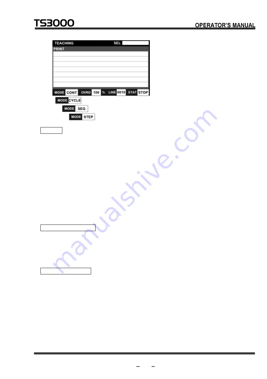
Page 170: ...ontroller TEACHING Test operation mode Displays the master mode and run mode currently being selected CONT Continuous operation CYCLE Cycle operation SEG Segment operation STEP Step operation Displays the speed override Displays the number of execution steps Displays the execution status RUN A program is in execution STOP The execution of a program is stopped Displays the name of the execution fil...

Page 171: ...tion Functional Explanation Select a file or program to be executed Operating Procedure Step 1 Displaying files Press the SEL key A list of the program files in the controller is displayed SEL Screen and Key Sheet Description of Display Displays program files 1 ...

Page 172: ...ist is sorted by name Each time the NAME key is pressed the sorting order changes between ascending order and descending order Display by file creation time Press the TIME key The file list is sorted by file creation time Each time the TIME key is pressed the sorting order changes between ascending order and descending order File search function Press the INPUT key Enter the head character string ...

Page 173: ...is operation cannot be performed while running a program 7 3 Selecting Run Mode Functional Explanation Changes over the run mode of automatic operation Operating Procedure Step 1 Calling the Mode Setting keys Press the MODE key The CONT CYCLE SEG and STEP keys are displayed on the menu of the key sheet Step 2 Selecting a mode to switch Select a mode to switch from the CONT CYCLE SEG and STEP keys ...

Page 174: ...he stop command is executed in the program program execution stops irrespective of the run mode currently selected The STEP mode cannot be set while running a program 7 4 Speed Override Functional Explanation Sets the speed override for automatic operation This function is useful to effect an additional override taking the programmed speed as 100 Operating Procedure Step 1 Selection of the speed o...

Page 175: ...alue of the key you pressed is copied to the command line and the key sheet changes to number input A fine value can be set on the command line If you want to directly enter a numeric value from the beginning without using the 5 10 15 20 and 25 keys on the keyboard press the NUM key Directly enter a value of the override rate on the command line ...

Page 176: ...fied speed override rate also takes effect in test operation and external automatic operation Unless it is changed the previous state is maintained Related Function The speed can be limited by the external signal low speed command When this happens the motion speed can be specified by the user parameter If the override speed set exceeds this low speed it is clamped there The external signal low sp...

Page 177: ...stops on a per instruction basis Step 1 Calling the Mode Setting keys Press the MODE key The CONT CYCLE SEG and STEP keys are displayed on the keyboard Step 2 Selecting step execution After pressing the STEP key press the EXE key in succession When a mode is switched STEP is displayed in the MODE field on the status bar at the bottom of the screen ...

Page 178: ... waiting for the RUN key is activated Cautions To stop the step operation press the ESC key to quit To execute a step in another run mode select the run mode again During step execution a step to be executed is displayed in the command filed of the teach pendant If a step operation is executed against a multitask program tasks are not changed over In addition the TASK command SWITCH command or any...

Page 179: ...unning conditions Set the conditions for executing the file selection run mode selection speed override setting Step 2 Servo ON Lightly grip the Enable switch of the TP3000 teach pendant and open the contact of the Safety switch When the Safety switched is lightly gripped the TP3000 s screen and key sheet switch to the JOG key sheet The servo turns on when the Servo ON switch on the TP3000 s main ...

Page 180: ...op key sheet of the TEACHING mode JOG Key Sheet TEACHING Mode Top Key Sheet Press the EXE key When program execution has started the STOP switch LED on the control panel goes out and the RUN switch LED goes on During execution RUN is displayed in the STAT field on the status bar TS3000 TS3100 Control Panel The TSL3000 does not have a control panel STOP SW RUN SW ...

Page 181: ...or the run mode and stops an automatic operation at the program end This function is used to stop the robot after the end of an operation Operating Procedure Step 1 Selection of the CYCLE key Press the MODE key The CONT CYCLE SEG and STEP keys are displayed on the keyboard Press the CYCLE key in succession Step 2 Entering the EXE key Press the EXE key When mode changing is executed CYCLE is displa...

Page 182: ...n at the end of the program SEG Stops execution immediately after the next operation instruction STEP Executes one step of the program at a time Cautions The cycle stop external control signal is inoperative in the test operation mode The SCOL program execution unit pre reads up to four 4 motion commands Therefore the program may be executed successively by up to three 3 cycles according to the cy...

Page 183: ...pleted the automatic operation stops When automatic operation is stopped the RUN switch LED on the control panel goes off Step 2 Stop execution Press the STOP key in the case of the teach pendant STOP is displayed in the STAT field on the status bar of the teach pendant screen The display of the STOP key on the key board changes to the RUN key Cautions In the test operation mode the stop external ...

Page 184: ...anel goes out and the STOP switch LED goes on STOP is displayed in the STAT field on the status bar of the teach pendant screen The display of the STOP key on the key board changes to the RUN key Cautions During program execution in the step mode the BREAK function is inoperative To stop the step operation press the EMERGENCY stop key or FEED HOLD key To restart execution after BREAK press the RUN...

Page 185: ...am execution can be restarted by canceling the feed hold When program execution has started the STOP switch LED on the control panel goes out and the RUN switch LED goes on RUN is displayed in the STAT field on the status bar of the teach pendant screen Cautions In the feed hold mode automatic operation step execution direct execution home return and manual guidance are invalid When the FEED HOLD ...

Page 186: ...rol panel and teach pendant and emergency stop external control signal are operative At the time of an emergency use whichever key you can get at quickest The EMERGENCY stop switches on the control panel and teach pendant are of a lock type When pressed they remain depressed and locked To reset turn and unlock the switch While the EMERGENCY stop switch is ON the servo power cannot be turned on 7 8...

Page 187: ...ution steps variables for a current file and allows execution of that program from the top This function is useful to execute a current file from the top of the program Operating Procedure Step 1 Selecting a program reset Press the PROG key Step 2 Execution of reset To reset press the EXE key in succession To cancel reset press the ESC key Cautions All variables used in the program are reset If yo...

Page 188: ...ution of step reset To reset press the EXE key in succession To cancel reset press the ESC key Cautions When you do not wish to execute the setting of initial conditions at the head of the program use the cycle reset instead 7 8 3 Cycle Reset Functional Explanation Resets all execution conditions excluding global variables for a current file and allows execution of the main program from the step i...

Page 189: ... be executed 7 8 4 Output Signal Reset Functional Explanation Turns off all of the user external output signals DOUT 1 to DOUT 164 The hand signals 201 to 204 are not turned off Operating Procedure Step 1 Selecting output signal reset Press the SIG key Step 2 Execution of output signal reset To reset press the EXE key in succession To cancel reset press the ESC key 7 8 5 Execution File Reset Funct...

Page 190: ...ght of the screen is emptied Cautions All variables being used in the program will be reset To start an operation select the execution file again 7 9 Execution Line Display LDISP Functional Explanation Displays the execution program Operating Procedure Step 1 Displaying the execution line Press the LDISP key The SCRLL and JUMP keys are displayed on the keyboard During program execution screen scro...

Page 191: ...onization between the execution line and screen scroll is cleared and the screen can now be scrolled using the up and down cursor keys The display of the SCRLL key changes to the CURRE key Step 3 Jumping during asynchronous display of the execution line Press the JUMP key during asynchronous display of the execution line Enter the line number you want to jump to on the command line and press the E...

Page 192: ...nizes according to the execution line Cautions RUN STOP and BREAK operations can be performed even during execution line display 7 10 Variable Monitor WATCH Functional Explanation Displays the values of a desired global variable Operating Procedure Step 1 Calling the WATCH function Press the WATCH key The WATCH screen and key sheet are displayed ...

Page 193: ...STE 85412 7 26 TP3000 series Robot Controller WATCH Screen and Key Sheet Description of Display Enter the global variable names you want to reference The values of global variables are displayed 1 2 ...

Page 194: ...nitor has been determined press the EXE key The current variable value is displayed according to the variable type The global variable signifies the variable real number type integer type position type coordinate type or load type as defined in the area flanked by GLOBAL END or by DATA END for the variable which can be edited by the DEDIT function in the program Real number and integer variable di...

Page 195: ... display Load variable display Step 3 Changing a variable value CHG Program values can be changed temporarily Position the cursor on a variable value and press the CHG key Change the value on the command line and execute to overwrite the value by pressing the EXE key ...

Page 196: ...orrect The CHG R function cannot be executed for the global variable yet to be initialized such as position type array variable which is not taught the robot The position type data can be changed in the range of 3 mm or 3 deg 7 11 Direct Execution DO Functional Explanation Directly executes a SCOL command by entering it through the teach pendant This function is used to establish the conditions le...

Page 197: ... Robot Controller Direct Execution Screen and Key Sheet Description of Display Command line for direct execution Step 2 Entering an SCOL program Using the NUM ALPH SYMBOL and other keys enter an SCOL program on the command line 1 ...

Page 198: ...eing entered on the command line turn on the servo and then press the EXE key in succession Step 4 Clearing the direct execution function When direct execution is performed the display on the command line is reset and the command line entry wait state is activated To quit the direct execution function press the ESC key Caution This function is inoperative in the feed hold or servo power OFF status...

Page 199: ... turn the servo power off beforehand At that time set the master mode to TEACHING with the mode select switch CAUTION 1 Make sure that no obstacle stands in the robot working range If any obstacle exists perform automatic operation at a slow speed and make sure that the robot will not collide with the obstacle at all 2 If the robot motion becomes abnormal during program execution press the EMERGEN...

Page 200: ...ed in the internal automatic mode are listed in the table below The basic operation of each of these functions is the same as those in the test operation mode In this section only the differences from the test operation mode are explained For more detailed operation procedure of each function please see Section 7 Test Operation Menu Description of Operation SEL Selects an execution program OVRD Pe...

Page 201: ...he controller INTERNAL Internal operation mode Displays the master mode and run mode currently being selected CONT Continuous operation CYCLE Cycle operation SEG Segment operation STEP Step operation Displays the speed override Displays the number of execution steps Displays the execution status RUN A program is in execution STOP The execution of a program is stopped Displays the name of the execu...

Page 202: ...perating Procedure Step 1 Selecting step execution Set the running conditions for file selection run mode selection and speed override Step 2 Servo ON Press the SERVO ON switch on the front panel of the controller Step 3 Execution of RUN Press the RUN switch on the front panel of the controller When the execution of the program starts the RUN LED goes on and the STOP LED goes off Also the executio...

Page 203: ...Explanation Sets the speed override for automatic operation When setting the programmed speed as 100 this function is used to apply an additional override The selections on the override key sheet are changed to the 10 25 50 75 and 100 keys at the time of internal automatic operation Operating Procedure Step 1 Selection of the speed override function Press the OVRD key The 10 25 50 75 and 100 keys ...

Page 204: ...CHING with the mode select switch CAUTION 1 Make sure that no obstacle stands in the robot working range If any obstacle exists perform automatic operation at a slow speed and make sure that the robot will not collide with the obstacle at all 2 If the robot motion becomes abnormal during program execution press the EMERGENCY stop pushbutton switch immediately to stop the robot NEVER restart the au...

Page 205: ...panel to The functions that can be used from the teaching pendant in the external automatic mode are listed in the table below The basic operation of each of these functions is the same as those in the test operation mode In this section only the differences from the test operation mode are explained For more detailed operation procedure of each function please see Section 7 Test Operation Menu De...

Page 206: ...d Key Sheet Description of Display Displays the mode of the controller EXE SIG External control signal mode EXE 232C Host mode Control by host computer EXE ETHER Host mode Control by host computer Displays the master mode and run mode currently being selected CONT Continuous operation CYCLE Cycle operation SEG Segment operation STEP Step operation Displays the speed override Displays the number of...

Page 207: ...e Observe one of the following manners to select a file a File selection by automatic start file Create an automatic start file having the name specified by a SELECT command in the controller in advance and then turn ON the power to the controller For more details on automatic start files please see Section 4 Program Editing b File selection by external signal Specify a file to be selected externa...

Page 208: ...ommand The internal automatic operation is a function of the TS3000 robot controller 9 3 Selecting Run Mode Functional Explanation Changes over the run mode of automatic operation Operating Procedure a External control signal mode When the cycle operation mode signal is turned on the cycle operation mode is selected When the same signal is turned off the continuous operation mode takes effect For ...

Page 209: ...ride in the internal automatic mode Specify a desired speed override beforehand in the internal automatic mode Then change over the MODE select switch b When using an automatic start file Create an automatic start file having the name specified by a SELECT command in the controller in advance and then turn ON the power to the controller For more details on automatic start files please see Section ...

Page 210: ...data communication In the external control signal mode only the startup signal is effective In the host mode only the startup by data communication takes effect The RUN switch at the front of the TS3000 is inoperative 9 6 Stop 9 6 1 Cycle Stop Functional Explanation Selects CYCLE for the run mode and stops an automatic operation at the program end Operating Procedure Step 1 Input of cycle operatio...

Page 211: ...up to three 3 cycles according to the cycle stop timing or the active program contents 9 6 2 STOP Functional Explanation Stops an automatic operation when the execution of the instruction currently being executed is completed This function is used for normal stop operation Operating Procedure Step 1 Input of STOP a Stop signal only in the external control signal mode Input the stop signal For deta...

Page 212: ...and Communication Manual respectively 9 6 3 BREAK Functional Explanation Immediately decelerates and stops the robot and stops an automatic operation This function is used to interrupt the automatic operation Operating Procedure a Step 1 Input of BREAK Stop signal only in the external control signal mode Input the break signal For details see the Interface Manual b In the case of the TP3000 Press ...

Page 213: ...n the TS3000 when FEED HOLD is input the STOP LED on the front of the controller goes on b Feed hold via data communication When in the EX 232C or EX ETHER mode feed hold can be performed via data communication For details refer to the Communication Manual When automatic operation stops the RUN LED on the front panel of the controller goes off The execution status of the teach pendant changes to S...

Page 214: ... Operating Procedure Turn on the Emergency Stop switch on the teach pendant or the emergency stop external control signal The TS3000 can also be stopped using the Emergency Stop switch on the front panel of the controller When Emergency Stop is input the servo power is turned off and the SERVO ON LED on the teach pendant goes off Additionally the SERVO ON SVON for the TSL3000 LED on the front pane...

Page 215: ...on is useful when you do not wish to execute the setting of the initial condition Also specify the GOTO RCYCLE command just before the END command not to execute the END command of the main program 1 4 Output signal reset Sets off all user external output signals DOUT 1 DOUT 164 The hand signals 201 204 will not turn off Operating Procedure a External control signal mode Turn on the input signal c...

Page 216: ...n Manual Cautions In the program reset mode all variables used in the program are reset If you do not wish to reset the variables use the step reset function instead If you do not wish to execute the setting of initial conditions at the head of the program use the cycle reset instead In the cycle reset mode use label RCYCLE in a desired step of the main program ...

Page 217: ...lete and rename files in the RAM drive and the USB drive inside a TS3000 folder Files can be copied between RAM and USB drives 10 1 Calling the File Operation Function Functional Explanation Calls the File Operation function Operating Procedure Step 1 Calling the File Operation function Press the FILE key on the top key sheet in the TEACHING mode FILE key ...

Page 218: ...ler File Operation Screen and Key Sheet Description of Display Displays the drive Displays file names Displays file sizes Displays dates of creation Displays the number of files Caution The File Operation function takes effect only in the TEACHING mode 1 5 4 2 3 ...

Page 219: ...ep 1 Displaying files in RAM Press the FILE key on the top screen in the TEACHING mode Section 10 1 A list of files registered in the RAM drives displayed Step 2 Displaying files in USB While a list of files in RAM is being displayed press the RAM USB key A list of files registered in the USB drive is displayed Each time the RAM USB key is pressed display switches between a list of files in RAM an...

Page 220: ... order and descending order Display by file creation time Press the TIME key The file list is sorted by file creation time Each time the TIME key is pressed the sorting order changes between ascending order and descending order File search function Press the INPUT key The cursor moves to the command line Enter the desired character string you want to search for on the command line Once the search ...

Page 221: ...USB drive create one 10 3 File Copy Functional Explanation Copies files in RAM to another RAM Copies files in USB to another USB Operating Procedure Step 1 Selecting a file Select the file you want to copy by moving the cursor up and down while a list of files in either the RAM or USB drive is being selected Once the file has been determined press the FILE COPY key Step 2 Entering the file name af...

Page 222: ...ing in progress press the ESC key Cautions If there is no TS3000 folder directory in the USB drive the USB drive selected in each operation will not be recognized Before performing file operation be sure that there is a TS3000 folder directory in the USB drive If there is no TS3000 folder directory in the USB drive create a TS3000 folder If the size of the copying data exceeds the memory capacity ...

Page 223: ...pying ends 10 4 File Delete Functional Explanation Deletes files in the RAM drive and files in the USB drive inside a TS3000 folder This function is used to delete unnecessary files when no free area is left in the RAM drive Operating Procedure Step 1 Selecting a file to delete Select the file you want to copy by moving the cursor up and down while a list of files in either the RAM or USB drive is...

Page 224: ...eletion press the ESC key Cautions It is not possible to erase a file being selected as the execution file If this happens the error message File already selected is displayed 10 5 File Rename Functional Explanation Changes the name of a file in the RAM or USB Operating Procedure Step 1 Selecting a file to rename Select the file you want to rename by moving the cursor up and down while a list of f...

Page 225: ...ursor moves to the command line Enter the desired file name to rename on the command line Once the file name has been determined press the EXE key A rename confirmation message appears Step 3 Execution of file renaming To execute file renaming press the EXE key To cancel file renaming in progress press the ESC key ...

Page 226: ...happens the error message File already selected is displayed and key entry is prompted It is not possible to rename a file to the file name being selected as the execution file If this happens the error message File already selected is displayed and key entry is prompted 10 6 File Copy between RAM and USB Functional Explanation Copies files between the RAM drive and the USB drive TS3000 folder Ope...

Page 227: ...ery time the key is pressed the arrow symbol at the center of the screen switches to set up the desired copy direction Step 3 Selecting a file to copy Press the SET key The file name is displayed in reverse video and set as a copy candidate Multiple files can be set as copy files File Transfer key Indicates the copy direction ...

Page 228: ...troller Step 4 Execution of copy Press the EXE key File copy is executed according to the direction of the arrow symbol at the center of the screen If a file having the same name already exists at the copy destination a message stating such will be displayed ...

Page 229: ...y all the files at a time press the EXE key Cautions If there is no TS3000 folder in the USB drive when the USB drive is selected in each operation the error message USB NOT FOUND is displayed and it is not possible to move to the File Transfer screen If the RAM USB key is pressed when a USB flash memory is not inserted into the controller a list of files in the USB drive cannot be displayed Even ...

Page 230: ...hing internal automatic operation and external automatic operation 11 1 Calling the Utility Functions Functional Explanation Calls the utility functions Operating Procedure Step 1 Calling the utility functions Press the UTILITY key The display of the key sheet changes to the utility function selection keys Step 2 Clearing utility function call Press the ESC key The utility function selection key d...

Page 231: ...ue and load factor ENC Used to display the servo encoder data For details see the Maintenance Manual provided separately PLC M Used to display the PLC data ZEROP Used to set the origin or home point Note This function is for maintenance use For details see the Maintenance Manual provided separately VER Used to display the system version ETHER Used to display the Ethernet status Note For details se...

Page 232: ...arameter editor is running 11 2 EXIT Key Functional Explanation Immediately quits each of the utility functions and moves to the top mode screen Operating Procedure Step 1 Press the EXIT key while executing a utility function Example Press the EXIT key on the key sheet in the AUX function Flow from utility function call to the EXIT key EXIT key TEACHING Mode Top Key Sheet Utility Function Selectio...

Page 233: ...ep 1 Moving from the utility functions to the top mode screen Press the Utility Shortcut key on the key sheet of each utility function The operation moves to the top mode screen without exiting the utility functions Step 2 Moving from the top mode screen to the utility functions Press the Utility Shortcut key on the key sheet of the top mode screen The operation moves to the preselected utility fu...

Page 234: ...elected the Shortcut key on the top mode key sheet does not take effect 11 4 Auxiliary Signal Display AUX Functional Explanation Displays the status of the signal auxiliary signal set in the user parameter U09 AUXILIARY SIGNAL and enables output operation Operating Procedure Step 1 Calling the AUX function Press the AUX key among the utility function selection keys The auxiliary signal display scr...

Page 235: ...ut signal Two output signal ports indicate double solenoids One output signal port indicates a single solenoid Displays arbitrary signal names described in user parameter U09 Example Content of USER PAR file Note 0 201 Hand out 1 Space Insert spaces in blank lines 19 lines will continue below For details see the User Parameter Manual 1 2 3 4 ...

Page 236: ...that can be operated switch Step 3 Auxiliary signal operation Press the AUX key assigned to the auxiliary signal you want to operate Each time the AUX key is pressed ON OFF of the auxiliary signal switches Step 4 Quitting the AUX function Press the ESC key The AUX function quits and the display returns to the utility function selection screen ...

Page 237: ...N including signals which are set for the double solenoid is OFF 11 5 External Input Output Signal Display I O Functional Explanation Displays the status of external input output signals Operating Procedure Step 1 Calling the I O function Press the I O key among the utility function selection keys The external input output signal display screen and key sheet are displayed I O Screen and Key Sheet ...

Page 238: ...that different items can be displayed in the left and right windows Step 3 Switching display items To switch display press the List Open key Step 4 Switching the focus of editing To switch the focus of editing press the Focus Change key This key operation takes effect for the window where there is the focus The light marks at the upper parts of the left and right windows indicate whether or not th...

Page 239: ...ists of five pages Pages are switched with the NEXT key Each time the NEXT key is pressed display switches Focus Change key Focus of editing is disabled Focus of editing is enabled 1st page general purpose output 2nd page extended output 3rd page system output 4th page field bus output 1 5th page field bus output 2 ...

Page 240: ...y is pressed display switches Step 7 Operation of the DOUT signal ON OFF operation can be performed for the DOUT signal Position the cursor on the output signal you want to operate and press the ON or OFF key Signal OFF state goes off Signal ON state lights green 1st page general purpose output 2nd page extended output 3rd page system output 4th page fieldbus output 1 5th page fieldbus output 2 ...

Page 241: ... below Step 10 HAND hand I O signal ON OFF operation can be performed for the hand output signal Position the cursor on the hand output signal you want to operate and press the ON or OFF key Step 11 MOTOR BREAK The motor of each axis can be released The motor brake operation takes effect in the following states The controller is in the TEACHING mode All axes are in the brake lock state when the MO...

Page 242: ... and by unlit green lamps for open contacts OFF The DIN and DOUT signals are shown 10 points on each line delimited by groups of five points and the number of the signal at the head of the signal string is displayed at the left end of the line The number of DIN and DOUT signal points displayed per page is 64 points The edited motor brake information is enabled when the MOTOR BRAKE CONTROL screen i...

Page 243: ...POS key among the utility function selection keys The current position current work and tool positions and the key sheet are displayed POS Screen and Key Sheet Description of Display Indicates the tool coordinate system being selected Indicates the work coordinate system being selected Indicates the current world position Indicates the base coordinate system Indicates the current work position Ind...

Page 244: ...1 7 Selecting and Clearing Work Tool Coordinates TRANS Functional Explanation Selects and clears the work and tool coordinates from the coordinate data in the program file being selected Operating Procedure Step 1 Calling the TRANS function Press the TRANS key among the utility function selection keys The coordinate data in the program file being selected is displayed Joint Position and Position F...

Page 245: ... system Displays a list of the coordinate data in the program file being selected Step 2 Setting up and clearing work tool coordinates For more information about operating procedures see Setting Up and Clearing Work and Coordinates Section 5 5 2 and Selecting and Clearing Tool Coordinates Section 5 5 3 in Section 5 Data Editing Caution This function is disabled unless a program is selected 1 3 2 ...

Page 246: ...ocedure Step 1 Calling the WK TM function Press the WK TM key among the utility function selection keys The current controller power ON time and program run time are displayed on the screen WK TM Screen and Key Sheet Description of Display Displays the power ON time of the controller Displays the program run time Indicates the command line for editing values 1 2 3 ...

Page 247: ... change has been determined press the EXE key Caution Edit each data within the following input ranges Hour 0 to 99999 Minute 0 to 59 11 9 Setting Up Date and Time DATE Functional Explanation Displays and sets up the current date and time Operating Procedure Step 1 Calling the DATE function Press the DATE key among the utility function selection keys The current date and time are displayed on the ...

Page 248: ...t Description of Display Displays the date Displays the time Indicates the command line for editing values Step 2 Editing the date and time Position the cursor on the item you want to change and press the EXE key Edit its value on the command line To confirm changes press the EXE key 1 2 3 ...

Page 249: ...99 2000 to 2099 Month 1 to 12 Day 1 to 31 Hour 0 to 23 Minute 0 to 59 11 10 Reproducing the Origin REORG Functional Explanation This is the maintenance function to reproduce the origin using the position information registered in advance in case the origin has been deviated For details refer to the Maintenance Manual Operating Procedure Step 1 Calling the REORG function Press the REORG key among t...

Page 250: ...roducing positions HOME3 and HOME4 are displayed Because HOME3 and HOME4 are the initial values which are set when shipped from the factory they cannot be edited in principle If they must be edited it is necessary to unlock the password Cautions For details of the display contents and setting see the Maintenance Manual To change the values of HOME3 and HOME4 it is necessary to unlock the password ...

Page 251: ...lues and sets up the joint limit values Operating Procedure Step 1 Calling the J LIM function Press the J LIM key among the utility function selection keys The current joint limit setting values are displayed on the screen J LIM Screen and Key Sheet Description of Display Joint limit value in negative direction Joint limit value in positive direction 1 2 ...

Page 252: ...ary joint is input in units of degrees and the linear joint in units of mm These limit values are used to limit the automatic operation range and teaching range of the robot for each joint They are factory set to the maximum working range for each axis Each joint set value is registered in the user parameter file file name USER PAR If any set value has been changed relevant data in the user parame...

Page 253: ...ays the torque electronic thermal and load factor of each servo motor Operating Procedure Step 1 Calling the MOTOR function Press the MOTOR key among the utility function selection keys The torque values of the motors are displayed first MOTOR Screen and Key Sheet Description of Display Displays the servo motor information 1 ...

Page 254: ...Press the THERM key The integrated thermal value of each motor is displayed Step 3 Displaying the load factor of each motor Press the LOAD key The load factor of each motor is displayed Step 4 Displaying the torque value of each motor MOTOR Function Default Screen Press the TORQU key The torque value of each motor is displayed ...

Page 255: ...on this screen This function is a maintenance function For details refer to the Maintenance Manual Operating Procedure Step 1 Calling the ENC function Press the ENC key among the utility function selection keys The servo encoder information and key sheet are displayed ENC Screen and Key Sheet Description of Display Displays the multi turn information Displays the single turn information Displays t...

Page 256: ...n of the encoder errors occurred so far number of errors is displayed The function menu on the key sheet changes To display the servo motor information again press the STATUS key Cautions For details on displayed information refer to the Maintenance Manual The multi return reset operation requires password unlock see Section 1 6 ...

Page 257: ...ating Procedure Step 1 Calling the PLC M function Press the PLC M key among the utility function selection keys PLC M Screen and Key Sheet Description of Display Indicates the display list Step 2 Selecting display items Position the cursor on the item you want to display and press the EXE key The displayed information is outlined below 1 ...

Page 258: ... ROBOT Input from TCmini to the robot main section G000 to G27F H ROBOT PLC Output from the robot main section to TCmini H000 to H27F X PLC INPUT Input from the external source to TCmini X000 to X07F X200 to X27F Y PLC OUTPUT Output from TCmini to the external source Y100 to Y17F Y300 to Y37F To change the displayed information press the LIST OPEN key ...

Page 259: ...r details on displayed information refer to the Simplified PLC Manual 11 15 Zero Position Setting ZEROP Functional Explanation Sets the zero position or origin This function is a maintenance function For details refer to the Maintenance Manual Operating Procedure Step 1 Calling the ZEROP function Press the ZEROP key among the utility function selection keys in the servo OFF state The ZERO POSITION...

Page 260: ... Description of Display Displays the encoder origin value of each axis Cautions To edit the origin values it is necessary to unlock the password see Section 1 6 For details on displayed information refer to the Maintenance Manual Servo ON and JOG operation are disabled during this function 1 ...

Page 261: ... 16 Version Display VER Functional Explanation Displays the system version Operating Procedure Step 1 Calling the VER function Press the VER key among the utility function selection keys VER Screen and Key Sheet Description of Display Displays the system information 1 ...

Page 262: ...he version information of the sequence system SERVO Displays the version information of the servo system TP3000 Displays the application version information of the TP3000 Each display item shows the system version name date and time of creation and checksum value from the left The date and time of creation is shown in the order of year month day hour and minute A check sum value is expressed in th...

Page 263: ...INE NO Displays M02 robot number specified in MACHINE PAR CONTROL NO Displays M01 controller number specified in MACHINE PAR Step 4 Displaying the sequencer information Press the SEQ key Display Item Description I O MODE Displays U11 startup sequence specified in USER PAR PROGRAM NAME Displays a sequence file name during run COMMON Displays the common type TYPE N or TYPE P SAFETY LOGIC Displays th...

Page 264: ...etting rotary SW on the slot B Ext2 C slot Displays the axis setting rotary SW on the slot C Ext3 D slot Displays the axis setting rotary SW on the slot D Ext4 E slot Displays the axis setting rotary SW on the slot E F slot Displays the axis setting rotary SW on the slot F 11 17 Ethernet Status Display ETHER Functional Explanation Displays the Ethernet information and status Operating Procedure St...

Page 265: ...0 OPERATOR S MANUAL series Robot Controller ETHER Screen and Key Sheet Description of Display Displays the Ethernet setting values of the controller s main body Displays the connection port information Displayed Data 1 1 2 ...

Page 266: ...tself that is written in the ETHERNET PAR E03 file FIRMWARE Version of the Ethernet unit firmware Displayed Data 2 Item Description Channel Indicates the Ethernet channel numbers from IP0 to IP3 OwnPort Robot port number Connect IP IP address of the other connected device Port Port number of the other connected device Step 2 Switching the Ethernet information at the connection destination Press th...

Page 267: ...de Displays the protocol type and open state TCP S indicates the server connection using the TCP protocol and TCP C indicates the client connection using the TCP protocol Status Displays the status of the following Ethernet port state transitions Closed Listen Syn Sent Syn Received Established Fin Wait1 Fin Wait2 Close wait Closing Last ACK Time Wait For more details on the meaning of each status ...

Page 268: ...nnection passes through a hub 11 18 Setting Up Payload for Manual Guide PYLD Functional Explanation Displays and sets up payload values for manual guide Operating Procedure Step 1 Calling the PYLD function Press the PYLD key among the utility function selection keys PYLD Screen and Key Sheet Description of Display Displays the work weight Displays the center of gravity and size of a work 1 2 ...

Page 269: ...s has been determined press the EXE key The edited data is reflected on the screen and U26 PAYLOAD FOR MANUAL OPERATION in the parameter file is updated at the same time Cautions The weight of a load is indicated in kg units and the offset is indicated in mm units The PAYLOAD setting value for manual guidance is stored in the user parameter file file name USER PAR If the PAYLOAD setting value for ...

Page 270: ... inadvertently erased or if the RAM disk is damaged due to low battery voltage or other cause Operating Procedure Step 1 Calling the BACKUP function Press the BACKUP key among the utility function selection keys in the servo OFF state BACKUP Screen and Key Sheet Description of Display Displays the status of backup No file EMPTY File present The number of files and the total number of bytes are dis...

Page 271: ...te state to the flash memory is displayed on the screen Step 3 Reloading backup Unlock the password and press the LOAD key A progress bar appears during reloading operation When the progress bar disappears reloading is completed Cautions When the backup file in flash memory is EMPTY load operation is disabled To use this function it is necessary to unlock the password see Section 1 6 Servo ON and ...

Page 272: ...vo OFF state The MARK ORIGIN screen is displayed MKORG Screen and Key Sheet Description of Display Indicates the current position settings Indicates the position settings after resetting The display changes according to the status joint position of the robot Numeric value display Resettable CANNOT RESET Unresettable NOT SUPPORT This function is not supported Indicates the results after resetting C...

Page 273: ...nce function For details refer to the Maintenance Manual Operating Procedure Step 1 Calling the BOOT function Press the BOOT key among the utility function selection keys in the servo OFF state The SYSTEM BOOT screen is displayed BOOT Screen and Key Sheet Description of Display Displays the current version name of the main system Displays the name of the upgraded version to be loaded to the main s...

Page 274: ...ons To use this USB BOOT function it is necessary to unlock the password see Section 1 6 For details on displayed information refer to the Maintenance Manual Servo ON and JOG operation are disabled during this function This function is disabled while the editor is running ...

Page 275: ... 8 the fault external control signal is output At the time of emergency stop the buzzer will not sound The fault signal will not turn on either To stop the alarm buzzer press the STOP switch on the control panel or execute the reset operation described in Section 12 4 Error Reset TSL3000 If an error occurs the buzzer sounds intermittently and the ALARM LED on the front panel of the controller goes...

Page 276: ... the error currently being detected Operating Procedure Step 1 Error display Press the ERROR key The code number and description of the error currently being detected is displayed on the screen Default Screen and Key Sheet Description of Display Displays the error code number Page number Displays the description of the error 3 1 2 ...

Page 277: ...escription contains more than one page the next page is displayed When the Up Arrow key is pressed the previous page is displayed Step 4 Ending error display Press the ESC key The screen moves to the top of the screen Error display takes effect regardless of the mode 12 4 Error Reset Functional Explanation Erases the display of errors which have been resolved It also stops the alarm buzzer If all ...

Page 278: ...orrected If a reset operation is performed when the cause of the error has not been removed the error will occur again In such a cause the error generation time is updated at the reset operation 12 5 Error Reset by External Signal Functional Explanation Resets all the errors whose cause has been removed Operating Procedure a Switch the master key and set the EXT SIG mode b Reset the error by turni...

Page 279: ...same effect can be achieved by turning ON the ALARM_RST signal when in the external signal mode Caution This function can be executed irrespective of presence or absence of the teach pendant 12 7 Error History Display Operating Procedure Displays the history number code number and time of error generation in the order in which errors occurred Operating Procedure Step 1 Displaying error history Pre...

Page 280: ...ey The date and time of error generation is displayed To return to the error description press the Left Arrow key Step 3 Switching to error display Press the CURRE key The display changes from error history to the error currently being detected Step 4 Clearing error history Press the CLEAR key The error history is cleared ...

Page 281: ...Press the 1 160 key while a compile error is occurring The details of the compile error are displayed on the screen Additionally the CURRE key is displayed on the Function menu of the key sheet For details about error descriptions refer to Appendix Compile Error and Compile Warning Messages in the Robot Language Manual Step 2 Exiting compile error detail display Press the CURRE key to return to th...

Page 282: ...rameter error will occur The details of a parameter error can be viewed on the error screen Operating Procedure Step 1 Parameter error display Press the 8 015 key parameter error detail display The name of the error causing parameter file and the error cause are displayed on the screen Open the corresponding parameter file with the parameter editor and fix the error causing parameter ...

Page 283: ...the parameter error Item count shortage the parameter file can be fixed automatically Press the UPDATA key during parameter error detail display The error causing parameter file is fixed automatically After the parameter has been fixed turn the power to the controller on off ...

Reviews: