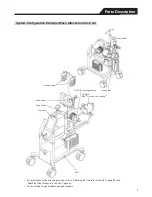
Parts Description
Number Name
Description
n
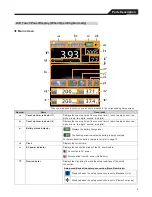
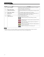
ABD status icon
Displays the setup conditions of the air bubble detector function, the status of
the alarm and the setup conditions of the safety connection.
The setup conditions and the status of the alarm
Displays the setup conditions of the safety connection at the left
side of the icon.
Also, the icon indicates that the alarm relating to the air bubble
detector function has not been triggered.
Setup conditions of the safety connection (Air Bubble
Detected Alarm)
Displayed when the safety connection is set to [Message
Only].
Displayed when the safety connection is set to [Pump
Coast].
Displayed when the safety connection is set to
[Clamp+Pump stop].
Indicates that a high priority alarm relating to the air bubble
detector function caused by the device has been triggered.
Indicates that a high priority alarm relating to the air bubble
detector function caused by the living body has been triggered.
Indicates that the air bubble detector function is off.
o
Auto priming icon
Starts and stops the intermittent operation (auto-priming) of the Drive Motor.
The icon is lit in green while auto-priming is performed.
p
Key lock icon
Locks the touch panel and the button operation.
The icon is lit in green while key lock is activated.
q
Pressure indicator (P1 and P2)
Displays the pressure value and the setup condition of the safety connection.
r
Setup conditions of the safety connection (Pressure Alarm (over
pressure/low pressure))
Over
pressure
Displayed when the safety connection is set to
[Message Only].
Displayed when the safety connection is set to
[Pump Coast].
Low
pressure
Displayed when the safety connection is set to
[Message Only].
Displayed when the safety connection is set to
[Pump Coast].
When the pressure measuring function is off, the whole pressure indicator is
displayed in grey.
s
Temperature indicator (T1 and T2)
Displays the temperature.
t
When the temperature measuring function is off, the whole temperature
indicator is displayed in grey.
11
Summary of Contents for CAPIOX EBS Circuit with X coating
Page 1: ...CAPIOX Emergency Bypass System Instructions for use...
Page 4: ...CAPIOX EBS Circuit with X coating Instructions for use...
Page 8: ...Structure Structure...
Page 25: ...EBS and X coating are trademarks of TERUMO CORPORATION 2019 XX...
Page 26: ...CAPIOX EBS Cannula Kit with X coating Instructions for use...
Page 29: ...CAPIOX Centrifugal Pump Controller SP 200 Instructions for use...
Page 175: ...Memo 146...
Page 176: ...147 Memo...


