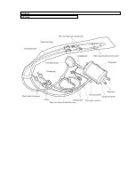
Connection
1.
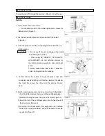
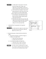
Close clamps of the arterial line (red) and venous line (blue)
from over the clean cover (Figure 15).
2.
Remove the clean cover pulling from the corner (Figure 16).
3.
Loosen each screw wing for the arterial line and the venous
line to remove the bypass connector (Figure 17).
4.
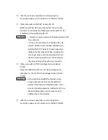
Connect the inserted arterial cannula (red) to the arterial line
(red) and the inserted venous cannula (blue) to the venous
line (blue) respectively (Figure 18) (Figure 19).
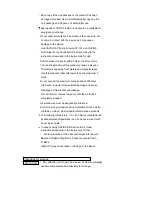
When the arterial and venous cannulas are connected
to corresponding lines, prevent them from kinking.
Otherwise, flow rate will not be secured, and it may
lead to damage of cannulas.
5.
Take off the cap (with air filter) from the 3-way stopcock for
removing bubbles, and remove bubbles remaining in the circuit
using a syringe.
The 3-way stopcock must be closed after
completing removal of bubbles.
6.
Fix the circuit to the patient or the bed.
Pay attention not to fold or kink the circuit.
Figure 15
Figure 16
Figure 17
Figure 18
Figure 19
CAUTION
CAUTION
CAUTION
Summary of Contents for CAPIOX EBS Circuit with X coating
Page 1: ...CAPIOX Emergency Bypass System Instructions for use...
Page 4: ...CAPIOX EBS Circuit with X coating Instructions for use...
Page 8: ...Structure Structure...
Page 25: ...EBS and X coating are trademarks of TERUMO CORPORATION 2019 XX...
Page 26: ...CAPIOX EBS Cannula Kit with X coating Instructions for use...
Page 29: ...CAPIOX Centrifugal Pump Controller SP 200 Instructions for use...
Page 175: ...Memo 146...
Page 176: ...147 Memo...


