background image

Other Operation Procedures 


  Battery-powered Operation 


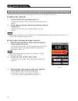
The Controller contains battery. If the AC power supply is lost or not sufficient, the AC power is automatically switched to battery 
power. The battery will supply power for about an hour. (On the condition that a new battery is charged for more than six hours, 
and then it is used with 2500 RPM motor speed and 4 LPM (L/min) flow)


The battery is recharged by connecting the Controller to the AC power source. For details about how to connect to the AC power 
source, refer to “Connecting to AC Power Cable” (page 31).


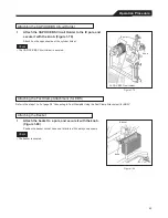
Display


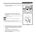
Connected to AC power/Charging


On battery


Control panel


Charging: lights up


LCD touch panel display


Charging: flashes


Switching from AC power to battery-powered operation


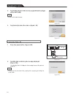
1. 

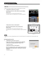
As soon as the power source switches to battery, “Battery- 
powered operation started” is displayed on the message 
area, and an alarm sounds. (Figure 2-11)


The status lamp flashes in yellow.


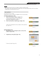
2. Tap 

[Battery-powered 

operation started] displayed on the 

message area. (Figure 2-11)


3. 

Tap [OK] to return to the main screen. (Figure 2-12)


When Cancel is tapped, it returns to step 1.


Figure 2-11


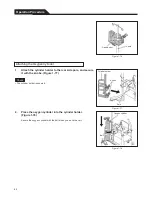
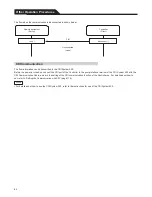
4. 

“On Battery” is displayed on the message area. 
(Figure 2-13)


The status lamp is lit in yellow.


Figure 2-12


Figure 2-13


72


Summary of Contents for CAPIOX EBS Circuit with X coating

Page 1: ...CAPIOX Emergency Bypass System Instructions for use...

Page 2: ...y or cardiopulmonary support to treat patients 18 years or older with Coronavirus Disease 2019 COVID 19 who have acute respiratory failure or acute cardiopulmonary failure where other available treatm...

Page 3: ...authorized for the above emergency use by FDA under an EUA and The CAPIOX EBS has been authorized only for the duration of the declaration that circumstances exist justifying the authorization of the...

Page 4: ...CAPIOX EBS Circuit with X coating Instructions for use...

Page 5: ...EBS Circuit with X coatingTM Instructions for Use 2019 XX Please read this Instructions for Use carefully before use and use this product according to the instructions described here...

Page 6: ...er Consult instructions for use Do not re use Do not resterilize Sterilized using ethylene oxide Keep away from sunlight Keep dry Fragile handle with care Do not use if package is damaged Temperature...

Page 7: ...roporous polymethylpentene hollow fibers a centrifugal pump to send blood and blood tubing It is intended for use during extracorporeal circulation for cardiovascular surgery and ECLS Extracorporeal L...

Page 8: ...Structure Structure...

Page 9: ...as flow should not exceed 20L min Excessive gas flow will bring about pressure increase in the gas phase allowing gaseous emboli to enter the blood phase Do not exceed a 15 C 27 F temperature differen...

Page 10: ...at flow rate lower than the maximum 7 L min Do not exceed the maximum pump speed of 3000rpm Otherwise it would increase blood damage and cause breakage of this product and leakage Do not install or r...

Page 11: ...xygenator and centrifugal pump This may cause heavy load at the connection parts of tubing and lead to leakage 4 Confirm that all the screws of 3 way stopcocks caps and connectors are fixed tightly an...

Page 12: ...he tube 12 7mm 1 2 or couplers to the water ports of CAPIOX EBS circuit Figure 8 a 8 b 7 Start water circulation through heat exchanger and circulate for at least 5 minutes Check for leaks Do not use...

Page 13: ...sor and flow connector Do not use gel which solvents are included such as alcohol thinner and amine etc These solvents may cause damage the sensor and connector 12 When using with CAPIOX Centrifugal P...

Page 14: ...ck on the priming line is open release the clamp 4 Fill the tubing circuit except the centrifugal pump and the oxygenator with priming solution It may take more time for priming if a large quantity of...

Page 15: ...parts 10 Hold the handle for rotation of the exclusive holder XX EB04 and unlock the rotation Then rotate the holder 90 degrees and replace it at the previous position Figure 13 Put away the handle fo...

Page 16: ...pump can be attached or detached In case that the bubbles still remain in the centrifugal pump set the centrifugal pump to the drive motor again and remove them circulating priming solution After the...

Page 17: ...line blue respectively Figure 18 Figure 19 When the arterial and venous cannulas are connected to corresponding lines prevent them from kinking Otherwise flow rate will not be secured and it may lead...

Page 18: ...clamped Otherwise negative pressure would be generated inside the pump and bubbles would be formedin the blood 2 Start the rotation of the centrifugal pump and set the pump speed at around 1000rpm 3 G...

Page 19: ...ump speed adjust the pump speed taking care not to cause back flow 1 Collect blood from the sampling line of the oxygenator Figure 21 Never collect blood from branch lines of the arterial line red and...

Page 20: ...for a longer period of time Termination of BYPASS 1 At the termination of circulation clamp the arterial line red by forceps etc taking care that no back flow occurs After that stop the pump by adjust...

Page 21: ...cannulas and close the clamps on the lines Loosen the screw rings of the arterial line and the venous line and then disconnect the lines 3 Connect the cannulas with a newly primed EBS circuit 4 Open...

Page 22: ...b pH SvO2 PvCO2 B E V Q Conditions Blood Hb pH SvO2 PvCO2 B E V Q Bovine Blood 12 1g dL 7 4 65 5 45 5mmHg 0 5mEq L 1 0 Blood Temperature 37 1 Conditions Blood Hb Tbi Twi Water flow rate Bovine Blood 1...

Page 23: ...2 7mm Couples connect fitting Blood outlet port Centrifugal pump Maximum pump speed Maximum outlet pressure Applicable console Applicable drive motor 3000rpm 800mmHg 107kPa CAPIOX SP Pump Console SP 1...

Page 24: ...irect or indirect incidental special general or consequential loss damage or expense from the use of this product TERUMO Corporation s sole obligation under this warranty shall be to repair or replace...

Page 25: ...EBS and X coating are trademarks of TERUMO CORPORATION 2019 XX...

Page 26: ...CAPIOX EBS Cannula Kit with X coating Instructions for use...

Page 27: ...he guide wire develops its lubricity only when the surface is wet Wet the surface of the guide wire before handling by filling the holder with heparinized saline in advance This device should only be...

Page 28: ...tion by operating at the circuit side Figure 9 1 Figure 9 2 For procedures and steps on extracorporeal circulation follow the instructions described in the Instructions for Use of circuit In case that...

Page 29: ...CAPIOX Centrifugal Pump Controller SP 200 Instructions for use...

Page 30: ...eference whenever necessary Read the instructions carefully before using the product and operate in accordance with instructions Perform maintenance and inspections to ensure safe use and extend the l...

Page 31: ...irculation 42 Centrifugal Pump Connection to the Tube Pack 43 Attaching the Centrifugal Pump to the Drive Motor 43 Attaching the ABD Flow Sensor 44 Attaching the Temperature Sensor CAPIOX Luer Thermis...

Page 32: ...m Setup List 105 Setting Auto priming 106 Setting the Coast Speed 108 Setting the Date and Time 109 Setting LAN 110 Setting the Communication with CDI 116 Setting the Language 118 Setting the Volume a...

Page 33: ...screen 7 5 inches Small and lightweight approximately 8 kg uses a lithium ion battery Auto priming function A flow sensor for the ultrasonic transit system is used Safety functions An air bubble sens...

Page 34: ...IOX centrifugal pump CAPIOX Hand Crank EBSTM Circuit with X coatingTM Gas blender Drive Motor Controller Cart For information on the attaching method refer to Attaching the Controller to the Cart page...

Page 35: ...hts up indicates the system has detected a low priority alert Yellow flashes indicates the system has detected a middle priority alert Red flashes indicates the system has detected a high priority ala...

Page 36: ...an AC power cable Pull out the AC power cable when shutting off AC power Bottom view Latch block Used for securing with the Cart an optional product Air inlet with filter 7 CDI port Connects to the CD...

Page 37: ...the motor speed at which back flow does not occur in accordance with clinical requirements Refer to Setting the Coast Speed page 108 1 When the motor speed is increased from 0 RPM to 2000 RPM 0 RPM C...

Page 38: ...r two digits minute two digits second two digits c Battery status indicator Displays the battery charge level The flashing arrow indicates the battery is being charged For details about the battery ch...

Page 39: ...bout the alarm messages refer to page 134 l Setup icon Opens the setup menu screen m Clamp status icon Displays the status of the Fast Clamp Indicates that the alarm of the Fast Clamp is not issued In...

Page 40: ...tion caused by the living body has been triggered Indicates that the air bubble detector function is off o Auto priming icon Starts and stops the intermittent operation auto priming of the Drive Motor...

Page 41: ...muted The muted condition of the alarm is awaken by tapping the icon However when two minutes have passed without resolving the alarming condition the alarm starts to sound again When another alarm i...

Page 42: ...ructions for use 1 Backup kit 1 Optional Products Drive Motor Catalogue number ME SP200M Magnets in the motor and in the centrifugal pump are joined magnetically and the rotating body in the centrifug...

Page 43: ...sor is attached to the blood circuit tube inner diameter 9 5 mm 3 8 inches Plug Cable Clamp on ABD Flow sensor Fast Clamp Catalogue number ME SPCLP01 When air bubbles are detected or back flow occurs...

Page 44: ...ensor connector Cable CDI Communication Cable Catalogue number XX SPCBL031 When transmitting the flow information to the CDI System 500 connect the CDI System 500 to the Controller Hand Crank Catalogu...

Page 45: ...Fast Clamp use this fixture with flexible arm The Fast Clamp can be attached in multiple configurations because of the flexible arm type Fast Clamp Attachment for EBS Catalogue number XX SPCLP01 When...

Page 46: ...ire system can be mounted on this cart Since infusion bags gas cylinders and gas blenders can also be attached the cart can support transportation during extracorporeal circulation Basket for accessor...

Page 47: ...ystem Make sure to use a pressure sensor which conforms to ANSI AAMI BP22 1994 If a pressure sensor that does not conform to the aforementioned standard is used this may result in decreased performanc...

Page 48: ...ould be used as far away as possible This system should use a power supply isolated from these devices and should obtain secure grounding Malfunction in this system caused by electronic interference m...

Page 49: ...rculating or priming if a significant amount of air enters the centrifugal pump causing the pump to idle and circulation to stop perform the following procedures After clamping the blood outlet line o...

Page 50: ...talogue No ME SPFAS01 ME SPFAS02 Temperature Sensor Cable Catalogue No XX SPCBL011 XX SPCBL012 Pressure Sensor Cable Catalogue No XX SPCBL021 Fast Clamp Catalogue No ME SPCLP01 CDI Communication Cable...

Page 51: ...ntroller ensure the connectors and plugs are not damaged If a connector pin is damaged or twisted replace the system with a spare one and do not use it This may result in decreased performance Since d...

Page 52: ...en and the Operation panel buttons etc of the Controller should not be pressed with excessive force and should not be operated with a pointed object It may cause damage to or failure of the display sc...

Page 53: ...flow and air bubbles When the air bubble detector function turns on pay attention to the handling of the blood circuit and the ABD Flow Sensor If a physical shock occurs to the blood circuit or to th...

Page 54: ...is system Do not subject this system to ethylene oxide gas EOG sterilization or high pressure steam sterilization or immerse this system in disinfectant solution The system may fail Do not let anesthe...

Page 55: ...cient the device shuts down and circulation cannot be maintained Warning Avoid sudden temperature changes even when operating within the system s indicated temperature specifications Condensation insi...

Page 56: ...lowing purposes Usage other than percutaneous cardiopulmonary support ECMO ECLS open heart surgery and aortic surgery Long term use in bridge to transplant or pending recover of the natural heart This...

Page 57: ...f the temperature measuring function of the channel to be used on page 37 When using the pressure measuring function after connecting the Pressure Sensor Cable and turning the power on turn the setup...

Page 58: ...e Applicable pressure sensor Pressure Sensor Cable Dedicated holder for applicable blood circuits For instructions on attaching other products refer to Attaching Other Products to the Cart page 61 1 L...

Page 59: ...the Controller with the Cart guide and place the Controller on the Cart Figure 1 3 b At this time the rubber feet are elevated Figure 1 3 4 Pull the lever of the Cart in the direction of the arrow to...

Page 60: ...ent If total power consumption exceeds the supply limit after the system is connected this may affect other equipment Additionally as the Controller operates on battery if the supply power is insuffic...

Page 61: ...he AC power cable When removing the AC power cable pull it out straight while pressing the latches as shown in the figure Figure 1 6 Figure 1 5 2 Plug in the AC power cable to the grounded AC power so...

Page 62: ...PIOX EBS Circuit Holder By using the screws removed in step 1 attach the Drive Motor with the screwdriver Attach the Drive Motor in the lower screw holes Figure 1 8 Figure 1 8 33 Connecting to Drive M...

Page 63: ...en removing the plug of the Drive Motor turn the lock ring counter clockwise until you hear a click and pull it out straight Figure 1 10 Using the pole clamp that comes with the Drive Motor 1 Attach t...

Page 64: ...he ABD Flow Sensor the Pressure Sensor Cable the Temperature Sensor the Fast Clamp the LAN cable and the CDI Communication Cable are not wet when connecting plugs to connectors If moisture is present...

Page 65: ...Clamp the LAN cable and the CDI Communication Cable to the Controller ensure the connectors and plugs are not damaged If a connector pin is damaged or twisted replace the system with a spare one and d...

Page 66: ...out straight while holding the outer ring of the plug of the Temperature Sensor Cable Figure 1 16 Figure 1 16 This section describes the step for using the pressure measuring function When using the...

Page 67: ...andle of the CAPIOX EBS Circuit Holder and insert the Fast Clamp Attachment for EBS as shown inthe figure Figure 1 19 Figure 1 19 2 Align the guide plate of the Fast Clamp Attachment for EBS to the ar...

Page 68: ...into the fast clamp connector on the rear panel Figure 1 23 Align the plug of the Fast Clamp with the slot of the fast clamp connector and insert the plug until you hear a click Do not forcefully inse...

Page 69: ...gure 1 26 b The Fast Clamp Arm is secured Figure 1 26 3 Attach the Fast Clamp to the Fast ClampArm Figure 1 27 a and secure it with the knob Figure 1 27 b The Fast Clamp is secured Figure 1 27 4 Inser...

Page 70: ...he plug pull it out straight while holding the outer ring of the plug of the Fast Clamp Figure 1 29 Figure 1 29 Perform the prior to use inspection by following Inspection Before Each Use Refer to pag...

Page 71: ...e 51 Continue to Starting Circulation page 55 42 YES Use the pressure measuring function YES Use the Fast Clamp Inspection Before Circulation Starts Before Each Use Auto priming Confirm the Setup Turn...

Page 72: ...any centrifugal pump other than the dedicated centrifugal pump CAPIOX centrifugal pump CAPIOX centrifugal pump as the component product of the CAPIOX EBS Circuit with X coating If a centrifugal pump o...

Page 73: ...low Sensor is attached at the blood outlet line Cautions Attaching the ABD Flow Sensor When attaching the ABD Flow Sensor apply enough vaseline to evenly coat the detection window of the clamp on ABD...

Page 74: ...amp on ABD Flow sensor to the bloodcircuit tube Figure 1 35 Figure 1 36 Fully insert the blood circuit tube into the detection window of the clamp on ABD Flow sensor Figure 1 35 CORRECT WRONG Figure 1...

Page 75: ...lation circuit line Figure 1 38 Figure 1 38 This section describes the step for using the pressure measuring function When using the pressure measuring function confirm that the setup of the pressure...

Page 76: ...the AC power source cannot be used sufficiently such as during transportation electric failure etc If the battery is depleted and charging is insufficient the Controller will not be able to operate by...

Page 77: ...d the setup of the safety connection Figure 1 44 Figure 1 43 Figure 1 44 To change the setup refer to the following sections of the user setup Setting Pressure Measuring Function page 85 Setting Tempe...

Page 78: ...started only when the motor speed is 0 Figure 1 46 2 Remove air from the branch lines while the centrifugal pump is rotating Remove the port cap of the sampling line of the oxygenator and attach a sy...

Page 79: ...a When using the pressure measuring function confirm that the setup of the pressure measuring function of the channel to be used is on Refer to Confirming the Setup page 48 1 Tap the setup icon on the...

Page 80: ...1 When using the Fast Clamp confirm that the setup of the Fast Clamp is on Refer to Confirming the Setup page 48 51 Do not attach the Fast Clamp to the blood inlet line of the centrifugal pump Air bub...

Page 81: ...ion If the lever does not return to the original position pull down the lever If it does not return to the original position a failure may have occurred Stop using the system immediately and contact T...

Page 82: ...to any position After moving to the position secure it by turning the knob of the Fast Clamp Arm clockwise Figure 1 56 b The Fast Clamp Arm is secured Figure 1 56 2 To change the direction of the Fas...

Page 83: ...f the lever does not return to the original position pull down the lever If it does not return to the original position a failure may have occurred Stop using the system immediately and contact Terumo...

Page 84: ...ctions for use of the centrifugal pump to be used 3 While monitoring the flow adjust the motor speedto achieve the necessary flow Figure 1 62 55 Note Check Inspection Before Circulation Starts Do not...

Page 85: ...as the inside of the centrifugal pump is negatively pressured Avoid sudden temperature changes even when operating within the system s indicated temperature specifications Condensation inside the sys...

Page 86: ...losed up position 3 Tap the setup icon Figure 1 64 and tap the Fast clamp icon on the Setup screen Figure 1 65 The Fast clamp screen opens Figure 1 64 Figure 1 65 57 When weaning be sure to clamp the...

Page 87: ...67 Figure 1 66 Figure 1 67 1 Press the power button Figure 1 68 Figure 1 68 2 Tap OK after confirming the message displayed Figure 1 69 Now Shutting Down is displayed on the message area and the powe...

Page 88: ...7 m of the IV hanger and secure it with the knob Figure 1 71 Two packs of 500 mL solution can be hung on the IV hanger Figure 1 71 59 Casters Keep the cart s casters in a locked position except when t...

Page 89: ...wer has a lock mechanism to prevent popping out Pull forward the lock release plate to open the drawer Figure 1 73 To close the drawer push the drawer back until you hear a click The Backup Controller...

Page 90: ...secure the products to the IV pole attach it below the level of the IV pole knob 1 Attach the gas blender to the front side poles Figure 1 75 or to the IV pole Figure 1 76 Be careful not to bend the g...

Page 91: ...nobs Figure 1 77 The cylinder holder is secured Figure 1 77 2 Place the oxygen cylinder into the cylinder holder Figure 1 78 Secure the oxygen cylinder with the belt when you move the cart Figure 1 78...

Page 92: ...teps 1 to 3 of page 38 Connecting to Fast Clamp Using the Fast Clamp Attachment for EBS 1 Attach the basket to a pole and secure it with the knob Figure 1 80 Position the basket so that it does not in...

Page 93: ...height where it does not come into contact with the caster or the ground Figure 1 81 64 Attaching the Hand Crank When using the Hand Crank attach it to a pole securely after ensuring there is enough s...

Page 94: ...such as motor speed flow pressure temperature and alarms etc as data The data can be output after weaning the status of Drive Motor stop page 78 LAN communication Communicates the records of alarms e...

Page 95: ...tivating the safety connection 1 When the Pressure Alarm is issued the motor speed is lowered to the coast speed The status lamp starts to flash in red and the alarm sounds while P1 Over Pressure Alar...

Page 96: ...the coast speed The status lamp starts to flash in red and the alarm sounds while Air Bubble Detected Alarm and Air Bubble Pump Coasting are displayed on the message area Figure 2 2 When the motor sp...

Page 97: ...s issued the Fast Clamp is closed up position and the Drive Motor stops The status lamp starts to flash in red and the alarm sounds while Air Bubble Detected Alarm Air Bubble Clamp Close and Air Bubbl...

Page 98: ...off The Air Bubble Detected Alarm can also be cleared by performing the step 5 or step 6 Figure 2 6 5 Pull up the lever of the Fast Clamp until you hear a click and remove the occlusion with the Fast...

Page 99: ...is issued the Fast Clamp is closed up position and the Drive Motor stops The status lamp starts to flash in red and the alarm sounds while Back Flow Clamp Close and Back Flow Pump Stop are displayed o...

Page 100: ...e original position pull down the lever If it does not return to the original position a failure may have occurred Stop using the system immediately and contact Terumo s service representative Figure...

Page 101: ...efer to Connecting to AC Power Cable page 31 Display Connected to AC power Charging On battery Control panel Charging lights up LCD touch panel display Charging flashes Switching from AC power to batt...

Page 102: ...ailure etc If the battery is depleted and charging is insufficient the Controller will not be able to operate by the battery during an emergency such as electric failure Connect the AC power cable to...

Page 103: ...on is lit in orange and the key lock turns on The key lock icon on the LCD touch panel display is lit in green at the same time Figure 2 14 Key lock icon Figure 2 15 If the key lock is turned on durin...

Page 104: ...ng stopping the timer 1 Tap the count up timer indicator Figure 2 17 The following figures show the count up timer 1 being used The timer starts and the elapsed time is displayed While the timer is ac...

Page 105: ...he timer count is reset and the indication returns to 00 00 00 00 Figure 2 25 Figure 2 24 Figure 2 25 Count Down Timer A count down timer can be set When the set time has passed you will be informed b...

Page 106: ...weight refer to Setting BSA page 93 Perfusion index indicator History While the power is on this function records data motor speed flow pressure temperature and events When the power is turned off the...

Page 107: ...AN cable and turn the setting of the LAN communication function of the Controller on For details about how to set up the LAN communication function refer to Setting LAN page 110 A direct connection be...

Page 108: ...ion is being established Communication between network equipment is conducted with TCP Network equipment serves as the TCP server and the Controller serves as the TCP client XML is used as the data fo...

Page 109: ...nvalid value is indicated The unit is LPM L min Pressure 1 ch Indicates pressure value 1 ch Pressure value unit The pressure value is from 250 to 900 mmHg from 33 3 to 120 0 kPa or NG and the value is...

Page 110: ...n connection is started is shown below The Controller transmits data to the TCP connection The Controller does not perform the delivery confirmation of the application level Therefore a response from...

Page 111: ...I System 500 Before the power is turned on connect the CDI port of the Controller to the pump interface terminal of the CDI System 500 with the CDI Communication Cable and turn the setting of the CDI...

Page 112: ...d off To maintain altered settings even after turning the power off make changes through the admin setup Icon name Function Initial setting value Reference page Flow Alarm Sets the threshold value of...

Page 113: ...y Displays the trend chart and the event list The history can be exported to a USB memory drive as log data page 95 Admin Setup Opens the admin setup menu page 99 The threshold value setup range 0 0 t...

Page 114: ...tting will not take effect The Low Flow Alarm is issued when flow has fallen below the set threshold value When the lower limit value is set at 0 0 LPM L min and the flow is 0 00 LPM L min the Low Flo...

Page 115: ...ing it off tap OK to complete the setting Figure 3 8 Setting the threshold value of the Pressure Alarm 4 Confirm that Alarm of the upper limit is selected Figure 3 10 Figure 3 9 5 Tap or to input the...

Page 116: ...rt 8 Tap Alert of the upper limit Figure 3 14 Figure 3 13 9 Tap or to input the upper limit value you want to set Figure 3 15 yellow indicates the threshold value of the Over Pressure Alertin accordan...

Page 117: ...s of the alert The following settings are available The on off status of the temperature measuring function The threshold value of the Temperature Alert setup range 0 0 to 50 0 C 1 Tap the Temperature...

Page 118: ...Temperature Alert in accordance with an input temperature Figure 3 22 6 Tap Alert of the lower limit Figure 3 24 Figure 3 23 7 Tap or to input the lower limit value you want to set Figure 3 25 yellow...

Page 119: ...OK the changes to the setting will not take effect Indication of the clamp status icon The icon indication changes in accordance with the status of the Fast Clamp For details refer to LCD Touch Panel...

Page 120: ...t Clamp Pump stop to the Over Low Pressure Alarm Air Bubble Detected Alarm and Back Flow Alarm can be set 1 Tap the Safety Connection icon Figure 3 31 The Safety Connection screen opens 2 Tap the resp...

Page 121: ...firmed in the list Also all of the settings can be reset to the admin setting 1 Tap the Alarm Setup List icon Figure 3 34 The Alarm Setup List screen opens To confirm the alarm settings 2 After confir...

Page 122: ...ge 9 1 Tap the BSA icon Figure 3 38 The BSA screen opens 2 Tap or to input height and weight values Figure 3 39 The height and weight can be set within the ranges below Height 40 0 to 250 0 cm Weight...

Page 123: ...rts Start changes to Stop Count down stops When count down stops Stop changes to Start b The timer returns to 0 hours 00 minutes 00 seconds c While counting down Returns to the set time of the timer a...

Page 124: ...layed tap OK or Cancel Figure 3 47 OK Returns the timer to the set time and restarts the count down Cancel Ends the use of the count down timer Tap OK or Cancel to stop the sound Figure 3 47 Data moto...

Page 125: ...3 50 Figure 3 49 Figure 3 50 Output data to USB memory The information recorded in the history can be exported as a log file When exporting log data insert a USB memory drive into the USB port on the...

Page 126: ...g data export process to the USB memory drive is started The export status to the USB memory drive is displayed by percentage Figure 3 55 When the data export finishes the screen will display a log ou...

Page 127: ...the system the log data of each case is stored separated by measured data such as flow values and the event data such as alarms alerts The maximum number of log data stored in the system is 50 cases...

Page 128: ...tting will be maintained even after the power is turned off Access to the admin setup is protected by passwords 1 Tap the setup icon on the main screen Figure 3 58 2 Tap the Admin Setup icon Figure 3...

Page 129: ...p the check box of Change Password to insert a check mark and tap OK Figure 3 62 When the input password is wrong Authentication failed is displayed Tap Return and restart from step 2 of Opening the A...

Page 130: ...mmHg Alert upper limit 300 mmHg Alert lower limit 70 mmHg Alarm lower limit 50 mmHg The setting will take effect after restarting page 103 On Off On mmHg kPa mmHg The setting will take effect instantl...

Page 131: ...8 Date Time Sets the date and time The date and time were set at the time of manufacture Japan time The setting will take effect instantly page 109 LAN Sets the connection environment of the LAN PC Se...

Page 132: ...g Function page 85 This section describes the setup procedures for the display unit of the pressure The pressure measuring function turns on off and the threshold values of the Pressure Alarm and the...

Page 133: ...w For details about how to set the preset value of the air bubble detector function refer to Setting the Air Bubble Detector Function page 90 This section describes the setup procedures for sensitivit...

Page 134: ...nctions alarm or alert threshold values and the settings of the safety connections can be confirmed in the list Also all admin setup values can be reset to the factory settings as follows For details...

Page 135: ...the Auto Priming icon Figure 3 74 The Auto Priming screen opens 2 Tap Time Setup Figure 3 75 Figure 3 74 3 Tap or and input the time for On s and Off s you want to set Figure 3 76 Figure 3 75 4 Tap OK...

Page 136: ...Auto Priming screen opens 2 Tap Motor Speed Figure 3 79 Figure 3 78 3 Tap or to input the motor speed you want to set Figure 3 80 Figure 3 79 4 Tap OK to complete the setting Figure 3 81 Figure 3 80...

Page 137: ...n opens 2 Tap or to input coast speed you want to set Figure 3 83 Figure 3 82 3 Tap OK to complete the setting Figure 3 84 Figure 3 83 Figure 3 84 If you do not tap OK the changes to the setting will...

Page 138: ...If you do not tap OK the changes to the setting will not take effect The date and time cannot be set while the motor is running Set the date and time before using the system for the first case in orde...

Page 139: ...N screen opens 2 Tap IP of PC Server Figure 3 90 The IP PC Server screen opens Figure 3 89 3 Tap the button of the address value you want to input Figure 3 91 The following screen examples show when t...

Page 140: ...3 94 Proceed to Setting the MAC Address Figure 3 94 If you do not tap OK the changes to the setting will not take effect Setting the MAC Address 1 Tap MAC of PC Server Figure 3 95 The MAC screen open...

Page 141: ...the boxes with the same operation as in steps 2 and 3 Figure 3 98 Figure 3 97 5 Tap OK to complete the setting Figure 3 99 Proceed to Setting the Communication Port Figure 3 98 Figure 3 99 If you do...

Page 142: ...CP of Controller Figure 3 103 The DHCP screen opens 2 Select On or Off Figure 3 104 The following screen examples show when Off is selected Figure 3 103 3 Tap OK to complete the setting Figure 3 105 W...

Page 143: ...utton is selected Figure 3 106 3 Tap or to input the IP address of the Controller you want to set Figure 3 108 The input range is 0 to 255 Figure 3 107 4 Input the values into all of the boxes with th...

Page 144: ...igure 3 111 3 Tap or to input the subnet mask of the Controller you want to set Figure 3 113 The input range is 0 to 255 Figure 3 112 4 Input the values into all of the boxes with the same operation a...

Page 145: ...setting values thus far are maintained but communication is not performed Figure 3 116 3 Tap OK to complete the setting Figure 3 118 Figure 3 117 Figure 3 118 If you do not tap OK the changes to the...

Page 146: ...u settings 2 Select On or Off of the CDI screen Figure 3 120 3 Tap OK to complete the setting Figure 3 121 Figure 3 120 Figure 3 121 If you do not tap OK the changes to the setting will not take effec...

Page 147: ...hanges to the setting take effect and the power is turned off automatically After the power is turned off turn the power on again Figure 3 123 Figure 3 124 The display language cannot be changed while...

Page 148: ...ake effect The volume differs according to the volume setting and the priority of the alarm The relationship of the volume setting and the alarm sound pressure is as follows Volume setting Large 65 to...

Page 149: ...move Turn the system off and disconnect the AC power cable and cables the Drive Motor the ABD Flow Sensor the Temperature Sensor Cable the Pressure Sensor Cable the Fast Clamp the LAN cable the CDI C...

Page 150: ...Storage conditions Ambient temperature 20 to 45 C relative humidity 10 to 95 RH non condensing 121 After Use Cleaning Method Do not expose this system to direct sunlight or ultraviolet irradiation for...

Page 151: ...ere are no foreign items or damage in the connectors 4 Turn the motor speed knob and check that it turns smoothly 122 Maintenance and Inspections Since this system is precision equipment it should not...

Page 152: ...main screen appears Confirmation items after the main screen is displayed The Serious System Error or the System Error is not issued The AC power lamp is lit and the AC power indicator is There is mor...

Page 153: ...sconnect the plug of the Drive Motor and turn on the power Drive Motor Disconnected is displayed on the message area and an alarm sounds Figure 5 2 2 Tap Figure 5 3 The alarm is muted Figure 5 2 3 Tur...

Page 154: ...trifugal pump into the Drive Motor and remove the clamp of the blood outlet line For instructions on installing the centrifugal pump refer to Attaching the Centrifugal Pump to the Drive Motor page 43...

Page 155: ...n 1 Attach the tube of the blood line to the Fast Clamp 2 Tap the setup icon Figure 5 8 3 Tap the Fast clamp icon on the Setup screen Figure 5 9 The Fast clamp screen opens Figure 5 8 4 Tap Clamp to o...

Page 156: ...ttery deteriorates regardless of use periodical replacement is necessary Replacement period of the battery differs based on the environment and frequency of use of the Controller The battery should be...

Page 157: ...s 7 Plug in the AC power cable to charge the battery until the charge lamp turns off Measure the elapsed time with a stopwatch The charge lamp turns off within six hours Since the battery is built in...

Page 158: ...en is displayed Is the Serious System Error or the System Error issued Is the AC power lamp lit and is the AC power indicator Is there more than 70 battery charge level Pass Fail Pass Fail Pass Fail P...

Page 159: ...tapping the Clamp Does the lever return to the original position after pulling it up until you hear a click If not does the lever return to the original position when it is pulled down Pass Pass Fail...

Page 160: ...t of use the time for replacement may vary Consult your Terumo s service representative regarding the need for replacement Service life of the Controller the Backup Controller the Drive Motor the ABD...

Page 161: ...ntative The time indication is not correct The time lags due to time accuracy Set the time again Refer to page 109 The motor speed is displayed as and the centrifugal pump does not rotate The Drive Mo...

Page 162: ...fer to page 51 The fast clamp function is not on Enable the fast clamp function Refer to page 90 The Drive Motor is running Execute the clamp after stopping the Drive Motor The key lock function does...

Page 163: ...ng AC power or by switching to the Backup Controller or to the Hand Crank High E968 Drive Motor Disconnected Detected that the Drive Motor is disconnected Turn off the power and reconnect the Drive Mo...

Page 164: ...and the motor speed changed to the coast speed Handle according to b When the safety connection of the Air Bubble Detected Alarm is set to Pump Coast page 67 High P1 Low Pressure Alarm 2 3 Detected th...

Page 165: ...rature Alert 2 3 Detected that the temperature has exceeded the setup temperature alert threshold T2 High Temperature Alert 2 3 On Battery Detected that the operation is continuously battery powered a...

Page 166: ...eady 2 3 Detected that the Fast Clamp is not prepared for use a Set the tube at the Fast Clamp and close the lid b Set the tube again and close the lid Low Clamp Error 3 Detected failure of the Fast C...

Page 167: ...uid temperature is 37 C and ambient temperature is 25 C Air bubble detector function Low sensitivity Detects air bubbles of 0 5 cm3 or more at flow 7 00 LPM L min or less Medium sensitivity Detects ai...

Page 168: ...transport conditions Ambient temperature 20 to 45 C Relative humidity 10 to 95 RH non condensing Pressure 70 to 106 kPa Power supply AC100 240V 50 60 Hz Battery lithium ion battery Run time One hour...

Page 169: ...o items that can be connected to connectors Accessories AC power cable 1 Instructions for use 1 Backup kit 1 Contents Backup Controller 1 Drive Motor without pole clamp 1 AC power cable 1 Screwdriver...

Page 170: ...d ME SYSTEMS see 5 2 2 1 c Guidance and manufacturer s declaration electromagnetic emissions The CAPIOX Centrifugal Pump Controller SP 200 is intended for use in the electromagnetic environment specif...

Page 171: ...al or hospital environment Surge IEC 61000 4 5 1 kV line s to line s 2 kV line s to earth 1 kV line s to line s 2 kV line s to earth Mains power quality should be that of a typical commercial or hospi...

Page 172: ...tes 1 At 80 MHz and 800 MHz the higher frequency range applies 2 These guidelines may not apply in all situations Electromagnetic propagation is affected by absorption and reflection from structures o...

Page 173: ...2 P 800 MHz to 2 5 GHz d 2 3 P 0 01 0 12 0 12 0 12 0 23 0 1 0 38 0 38 0 38 0 73 1 1 2 1 2 1 2 2 3 10 3 8 3 8 3 8 7 3 100 12 12 12 23 For transmitters rated at a maximum output power not listed above t...

Page 174: ...for static electricity Potential equalization terminal Alternating current Symbol Description of Symbols Direct current Consult instructions for use Contents Temperature limitation Relative humidity l...

Page 175: ...Memo 146...

Page 176: ...147 Memo...

Page 177: ...td 14th Floor Geleximco Building 36 Hoang Cau Street O Cho Dua Ward Dong Da District Hanoi Vietnam Tel 84 4 3936 1643 Fax 84 4 3936 1641 TERUMO MARKETING PHILIPPINES INC Unit 3203 A B West Tower The P...

Reviews: